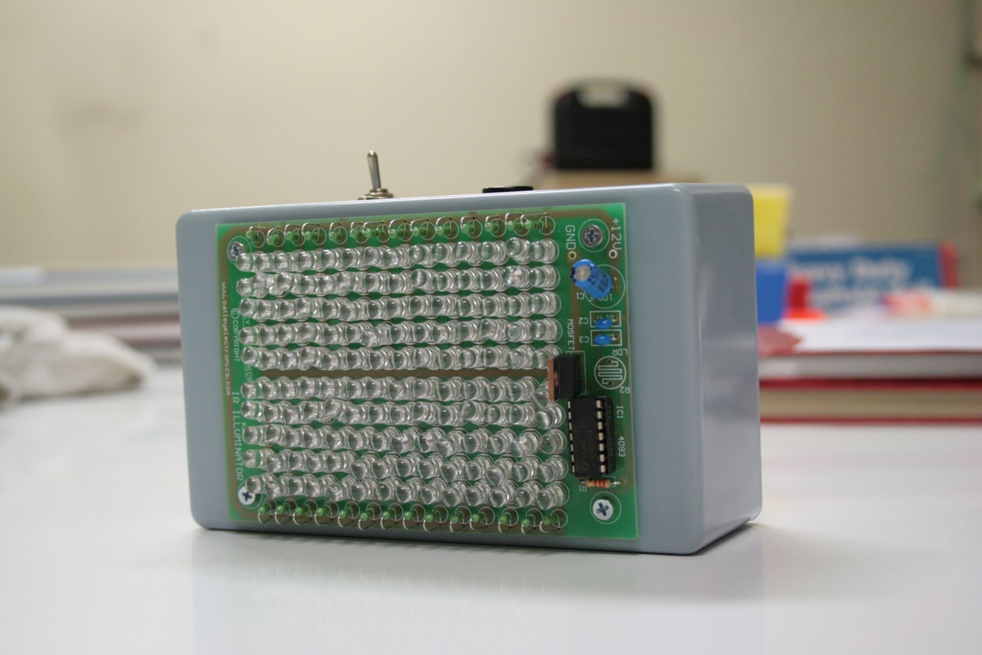
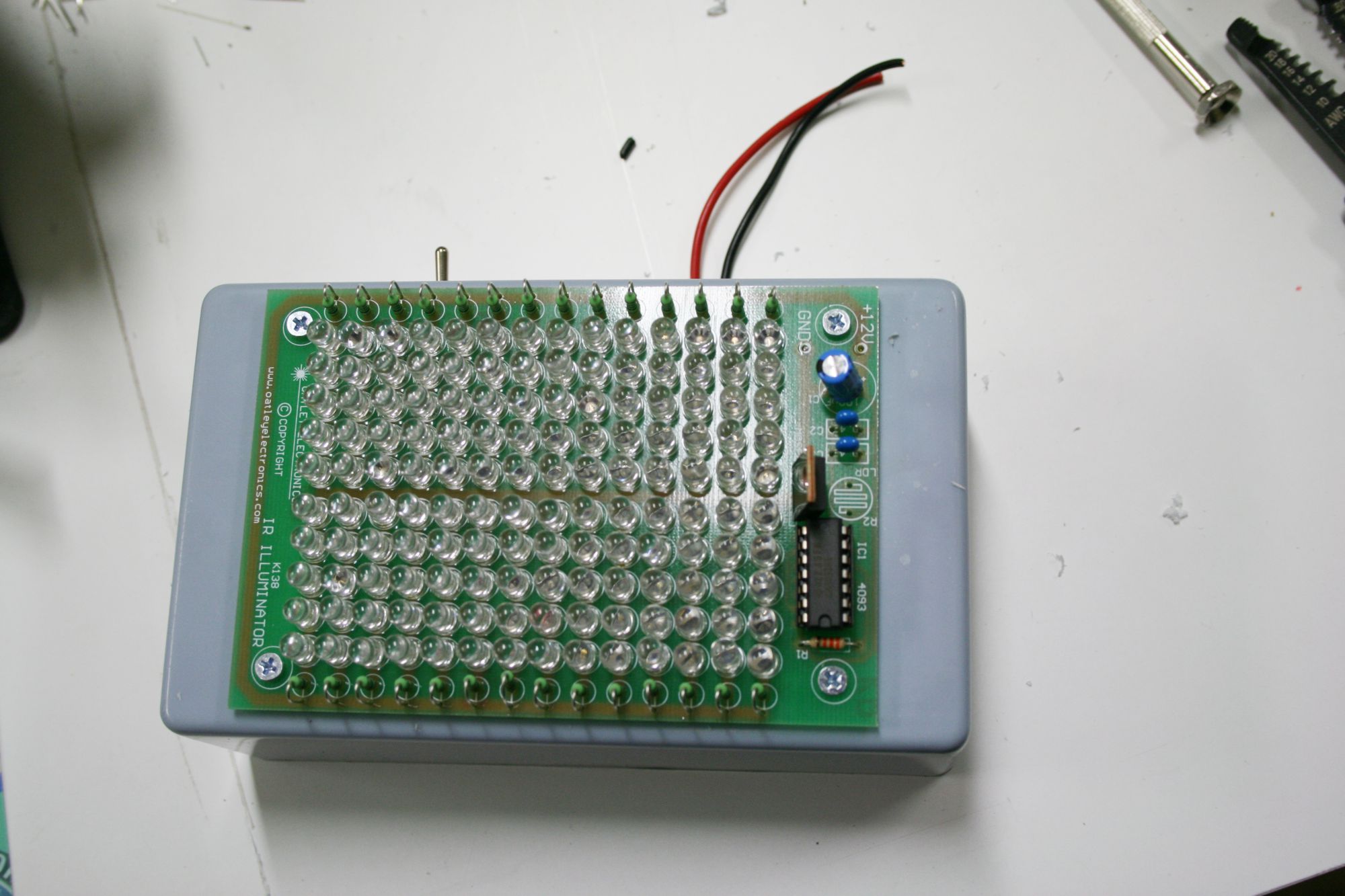
This is the second of a post in which we are looking at how to construct your own infrared light source from a commercially available kit. Below is a picture of the completed infrared light source we are about to make. It has 140 x 850nm infrared LEDs. As described in part 1 of this post, the manufacturer of this kit decided, for reasons best known to themselves, to ship the kit without any instructions. Since posting the first part of this tutorial here the hits on my web site by people looking for information on how to assemble IR light sources have actually become the most frequent reason for people finding my web site. So clearly there is an interest in IR lights. Hopefully this tutorial will help a bit.
The light made from the kit shown here is actually a very good IR light source, so if you are looking around for a simple but bright IR light source then you could certainly do a lot worse than this one. I have used it for the last year in my research and two other labs in the department are currently borrowing them, one to dissect retinal tissue under infra red light (so you don’t bleach the photoreceptor pigments), and the other to film mice swimming in complete darkness, so they are certainly worth considering.
Below is a picture of the finished light source so you can see what we are working towards. (NB: Click on the images for a bigger version)
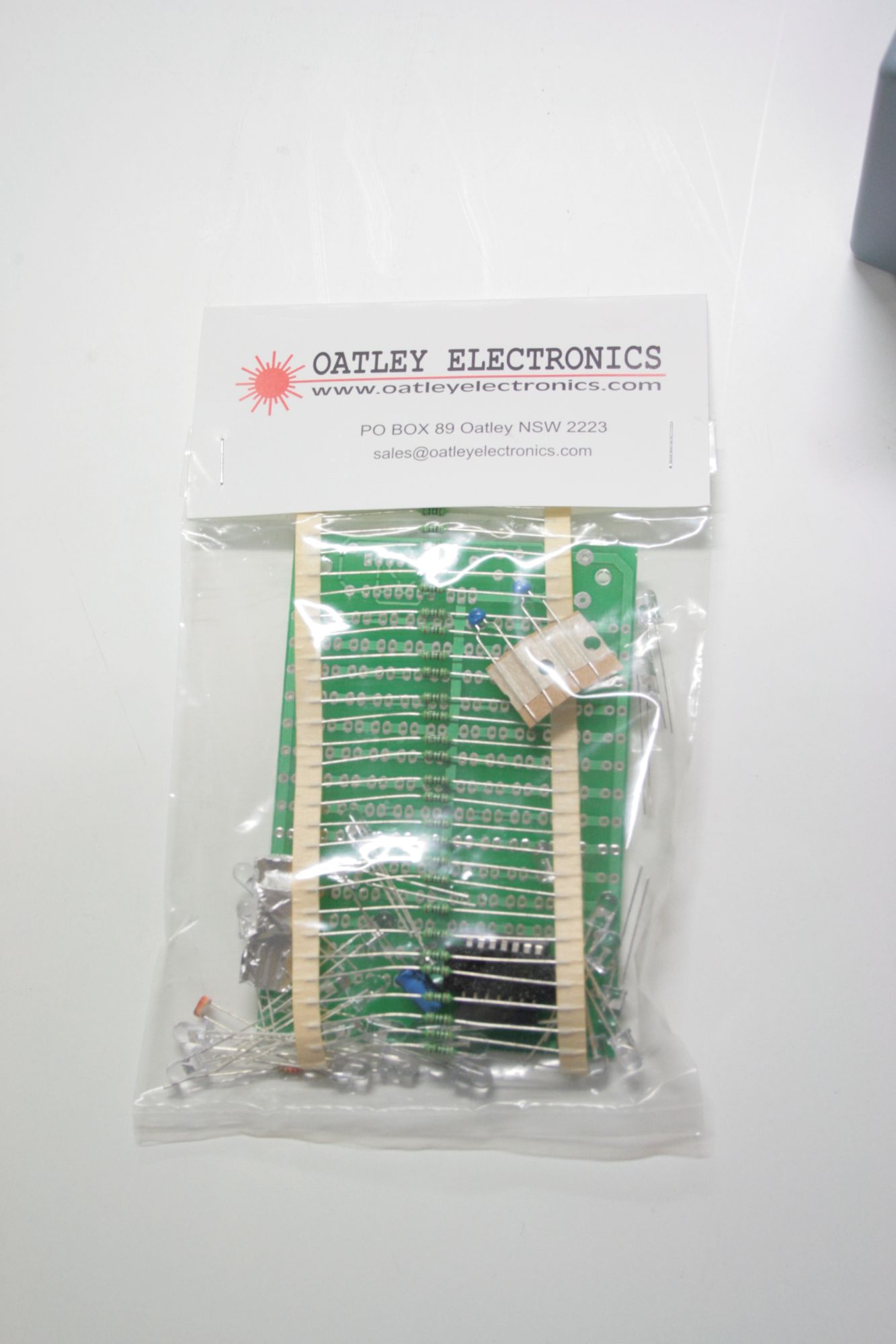
Below is a picture of the kit as it arrived by post.
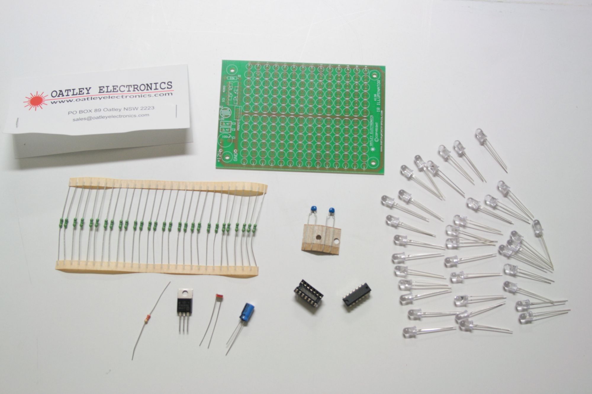
When we unpack the kit we find that it has the following items:
I will quickly mention what each of the components are and then we can have a look at how to put them together.
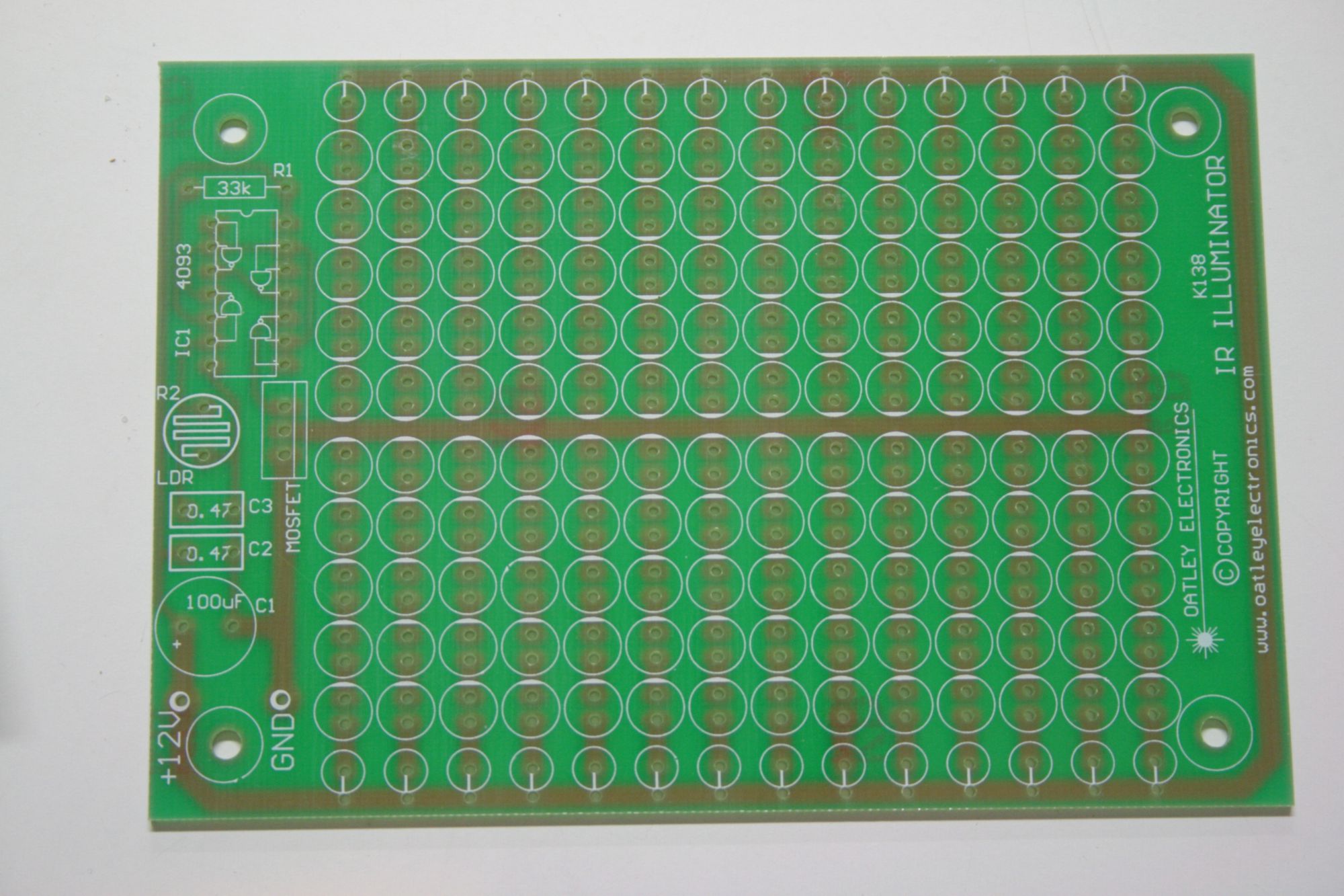
The first component is the printed circuit board. This is the bit where we will plug all the other components into to create the circuits that will turn on our IR LEDs. We will come back to this and look at where everything goes in a little while.
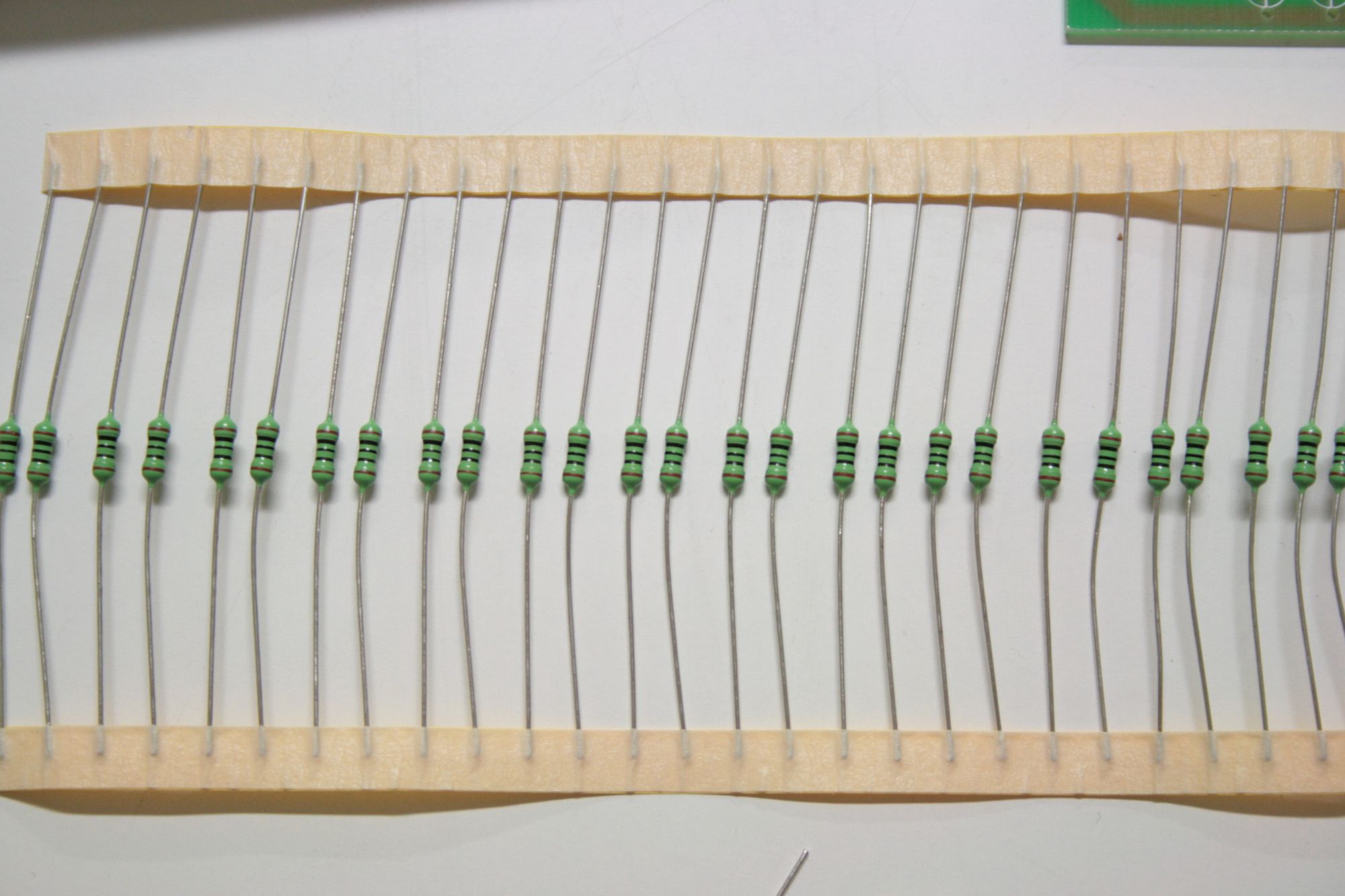
The strips of small, green cylindrical things are a series of resisters which help control the current that passes through our LEDs.
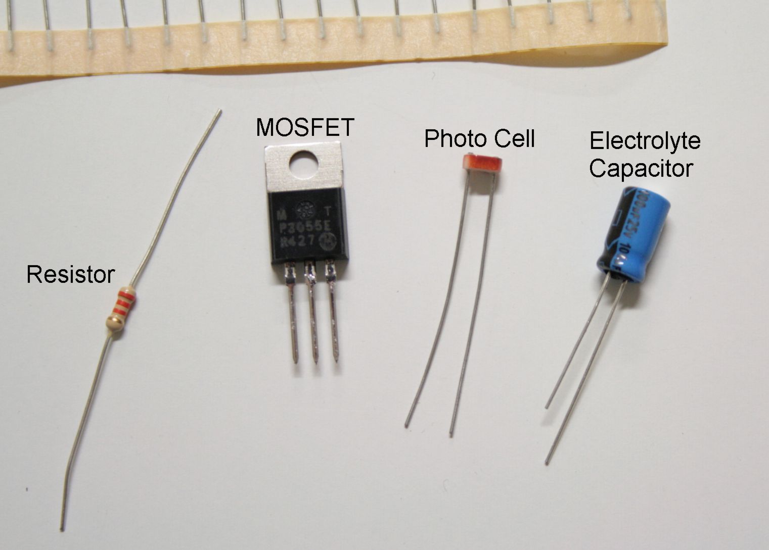
The next few items are another 1) stronger resister, 2) a Metal Oxide Semiconductor Field Effect Transistor (MOSFET), 3) photo cell (eg http://www.futurlec.com/Photocells.shtml) and 4) an electrolyte capacitor.
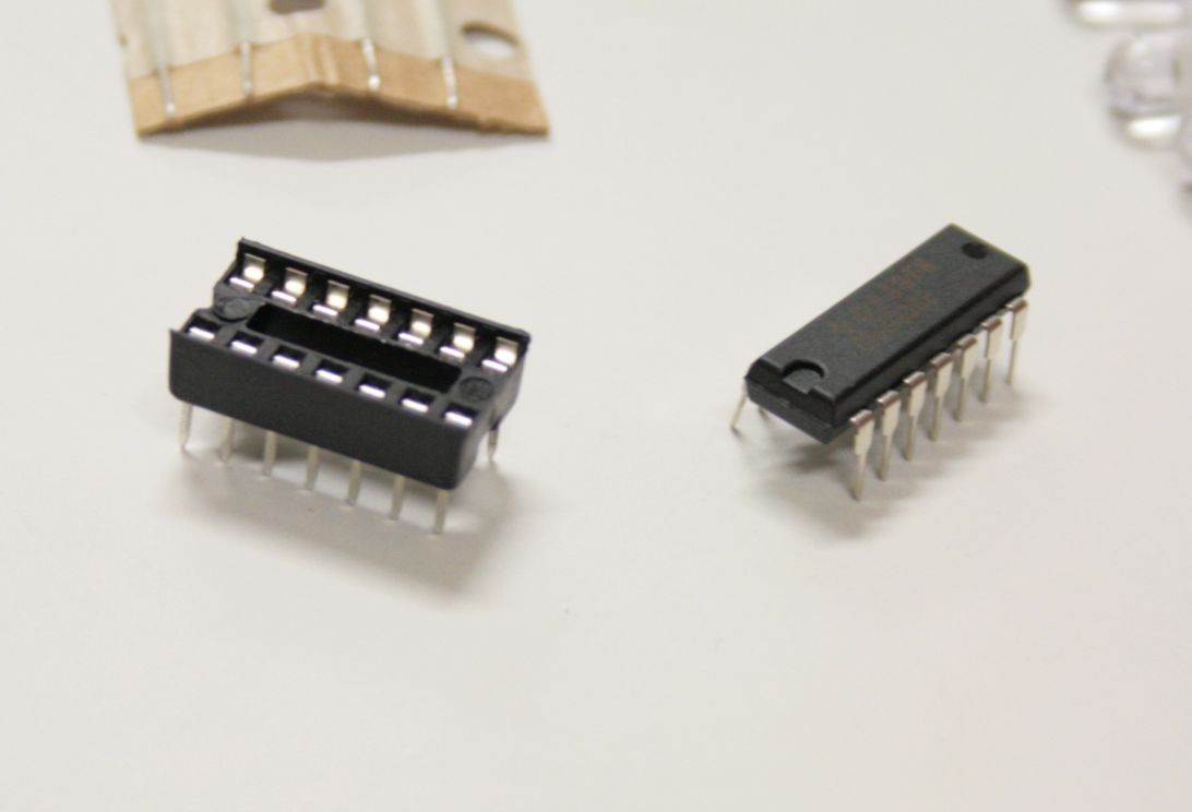
Integrated circuit chip.
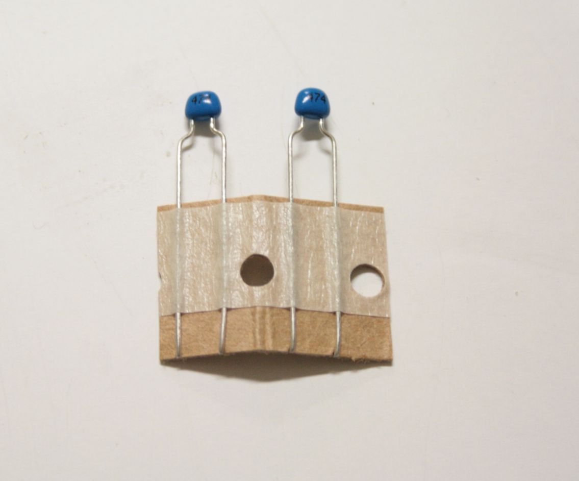
Ceramic Capacitors
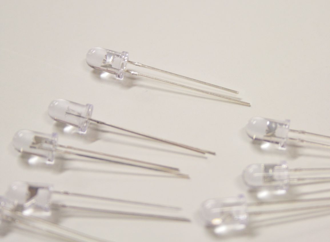
880nm IR LEDs (these are the LEDs that came with the kit which I replaced with 850nm LEDs since I wanted 140 of them and the kit only came with 35 LEDs).
Additional items
In addition to these items that arrived with the kit, I also wanted to attach the circuit board to something so I bought a case, switch, and power plug socket. I bought a power supply from the electronics guy at work and since I wanted to run two IR light sources from a single power supply I also wanted to make a double adapter to split the power cord, so I bought another case, three more power sockets, some lengths of electrical cable and 4 plugs (cable not shown in figure below). I will show how all this goes together later in this tutorial.
Completed light source showing what we are aiming for.
Assembling the Light Source
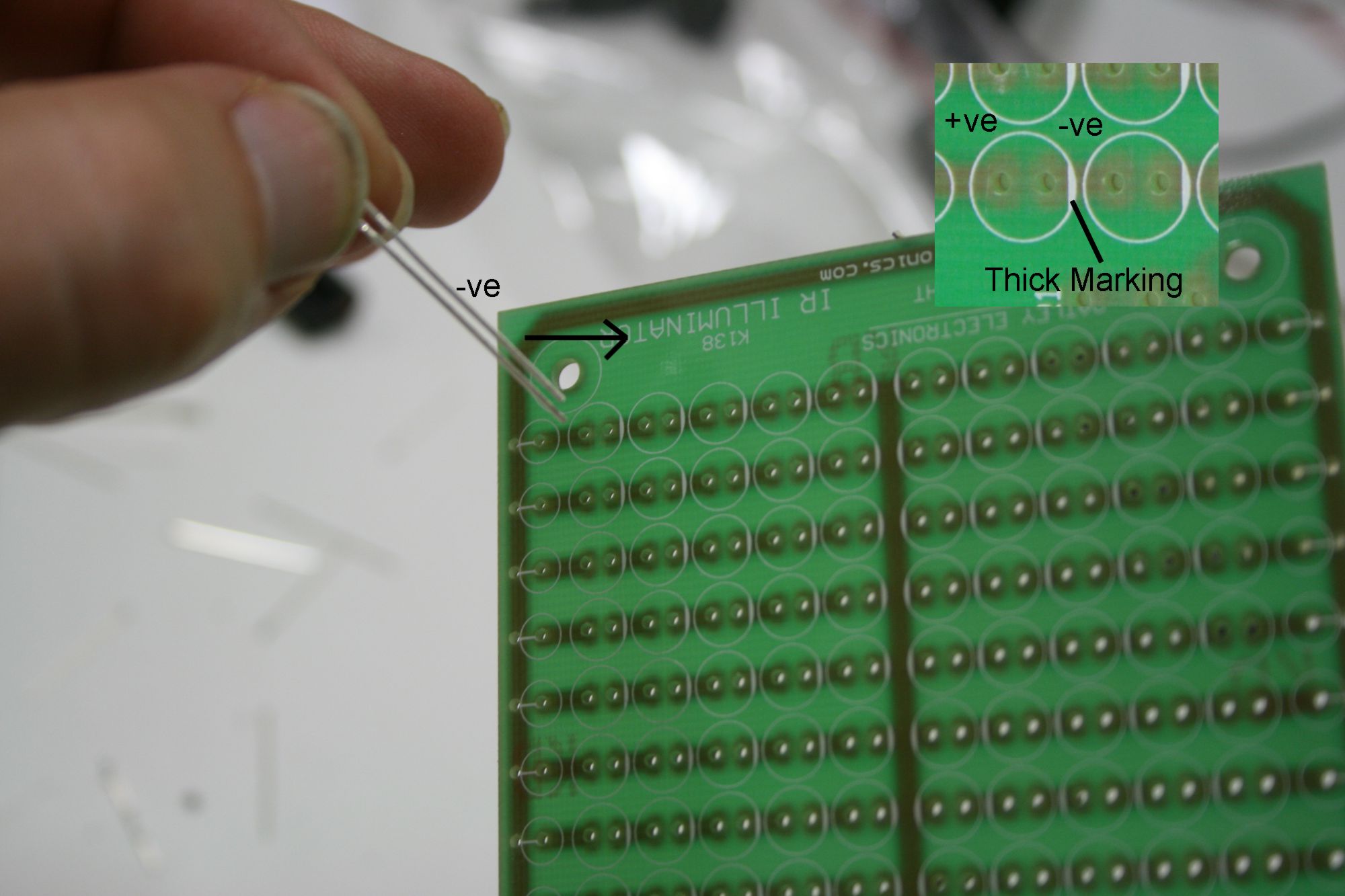
We will first of all install all the LEDs. Electric current only flows in one direction through an LED so it is important to get them the right way around otherwise the light source won’t work. If you look at the prongs coming out the bottom of an LED (the leads) you will notice that one lead is shorter than the other. Also, on the side with the short lead the there will be a flat surface on the side of the lens. These things indicate the negative lead. The negative lead (ie the short lead) should go towards the negative side (the ground) of your circuit. The holes that the LEDs are inserted into are marked with a thick line on the negative side. To insert the LEDs then just insert the short lead into the marked side of the holes as demonstrated in the photo below.
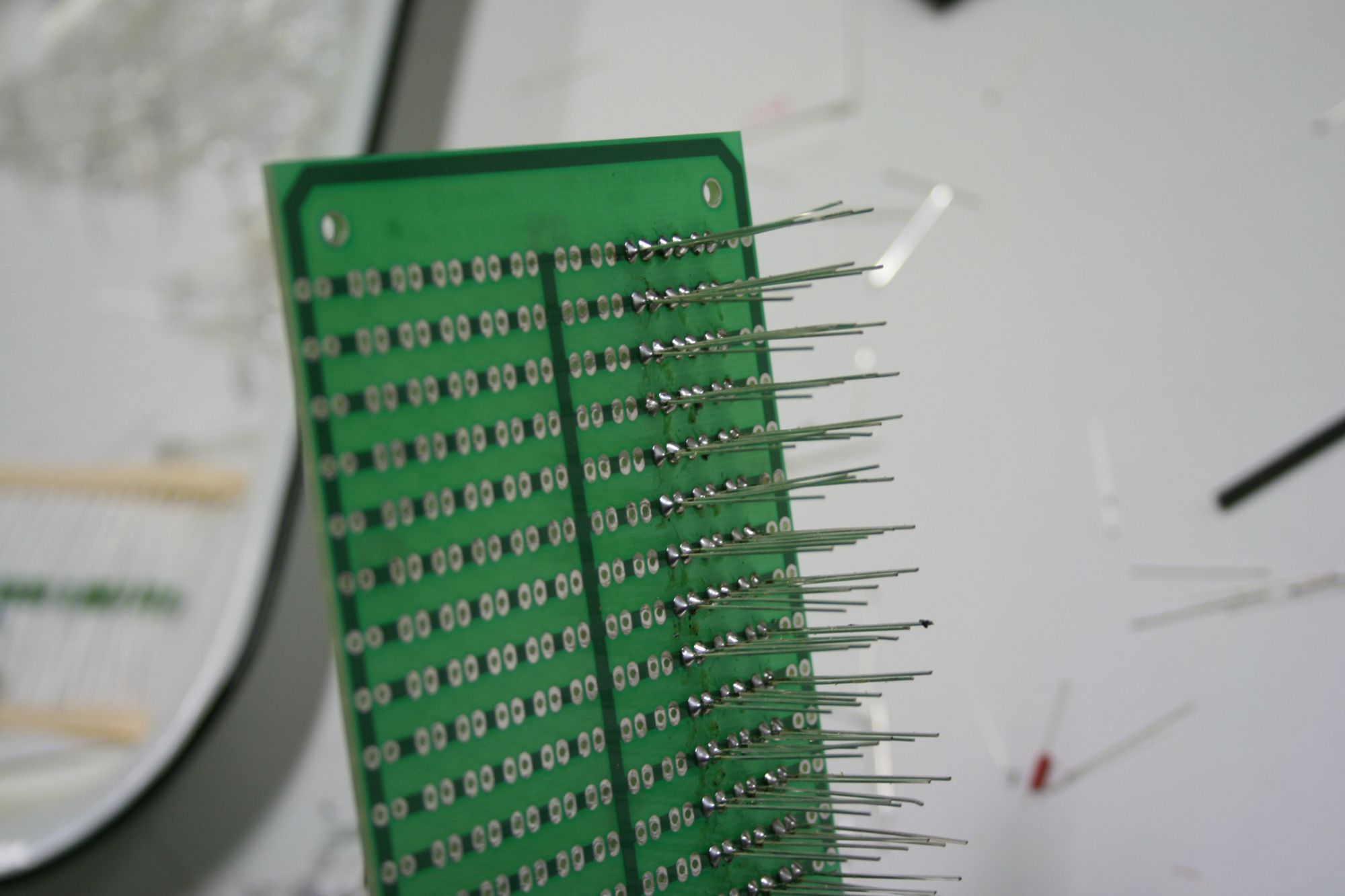
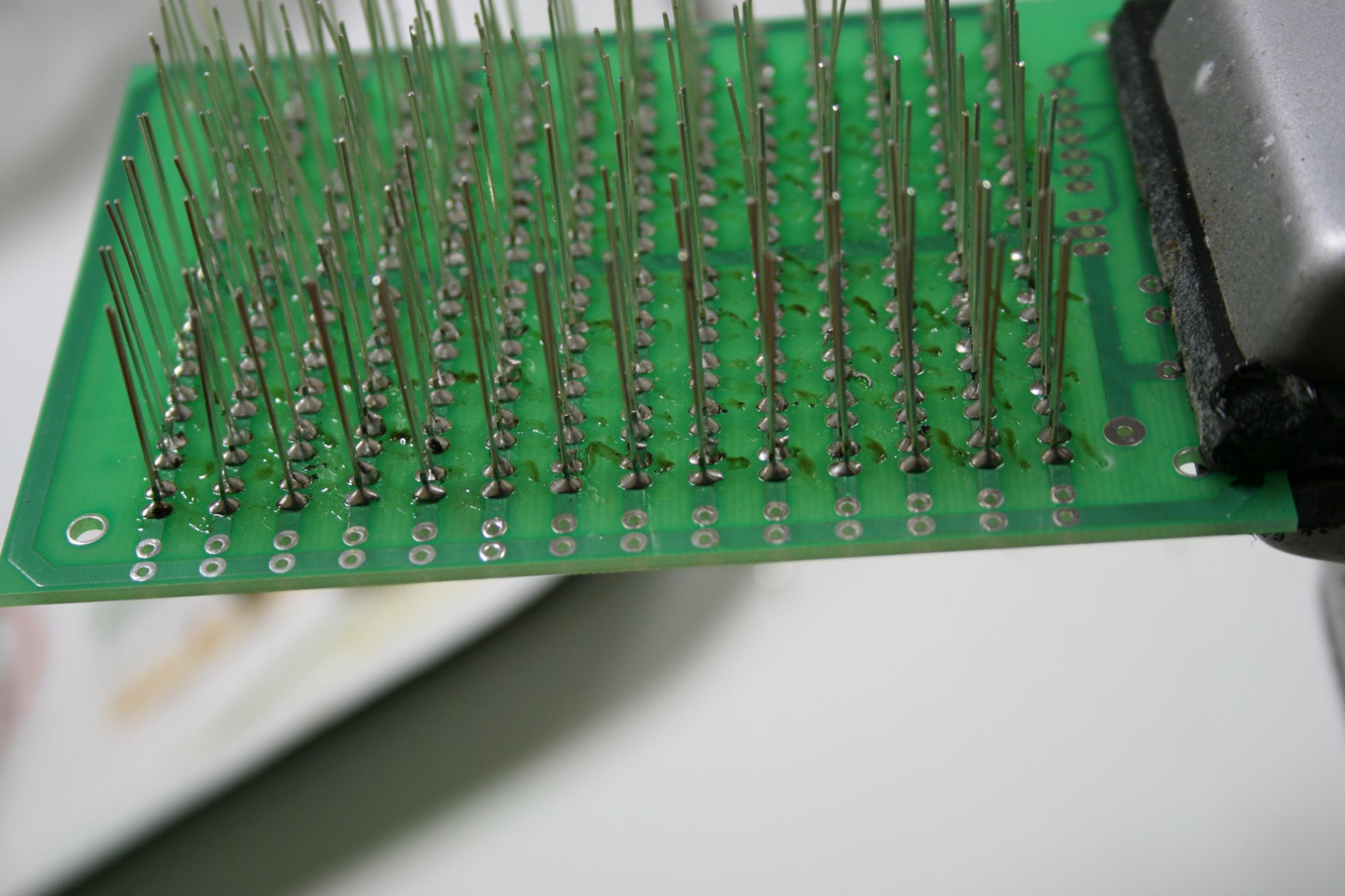
Below, I have half done the first side of the board. You can see the leads of the LEDs soldered into position. There are a heap of web sites that show how to solder correctly (eg http://www.ee.latrobe.edu.au/~djc/Soldering/how_to_solder.htm). This is an important skill to master in order to put together your own electronics. In order for an electronic device to function it must conduct electricity. If you don’t solder correctly you will get short circuits or “dry joints” where the solder doesn’t join the two components, both of which will prevent your device from working. So do take the time to make sure you are soldering correctly.
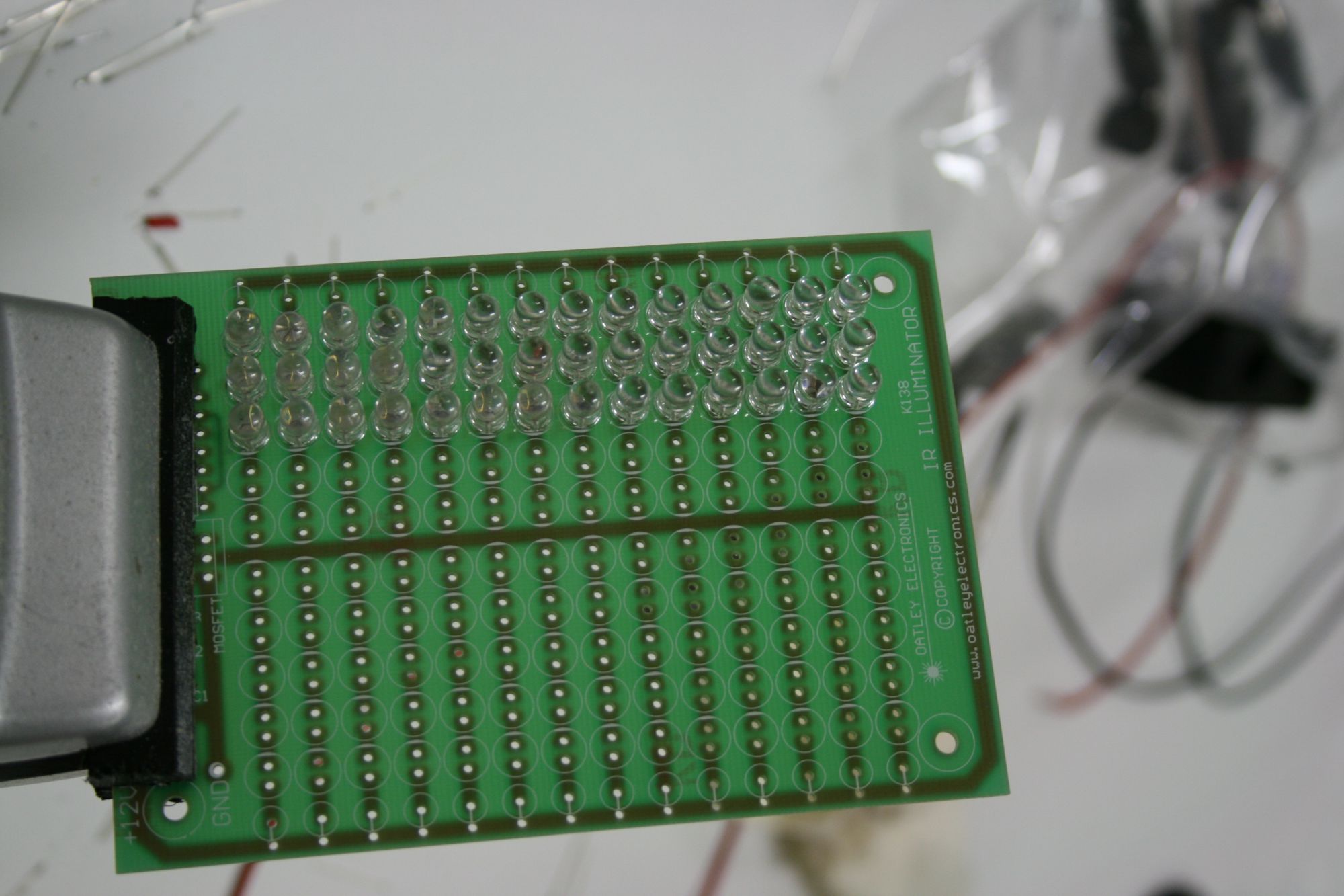
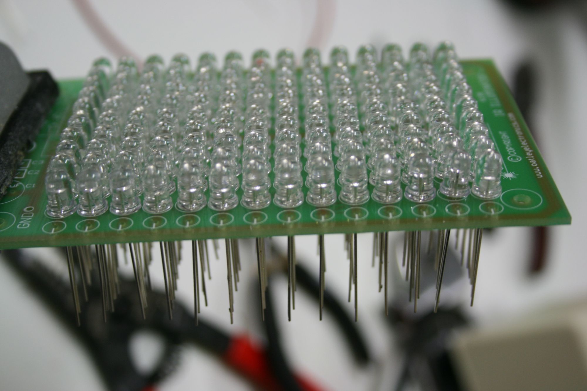
The LEDs from the top.
Below is the board from the bottom with all the LEDs soldered into place.
The same board from the top.
My girlfriend Tala
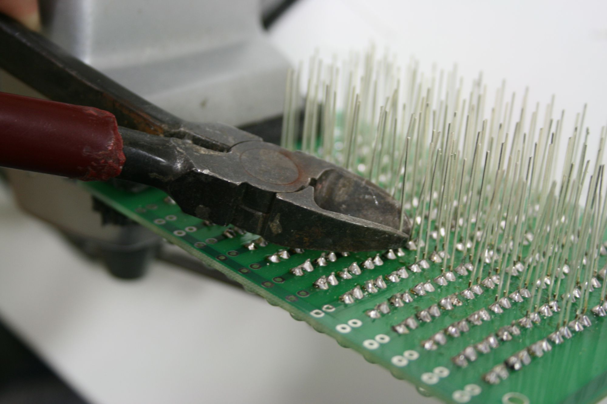
Once all the LEDs are soldered into the board you can clip off the excess leads with a pair of wire clippers. NB: SAFETY NOTE. Make sure you are wearing safety glasses when you do this as the bits of sharp wire shoot all over the place and can easily damage your eyes.
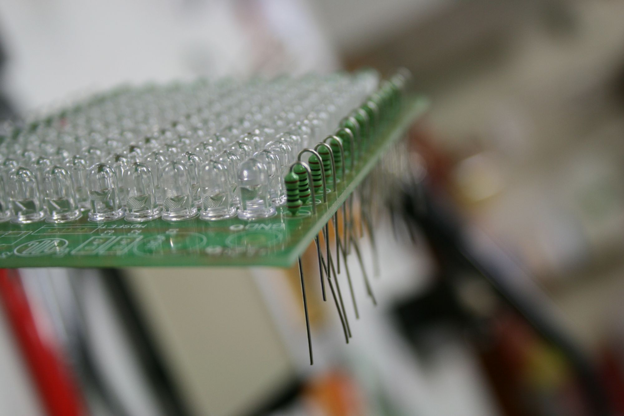
Next we then put in the resisters through the holes at the end of each row of LEDs. Resisters don’t have a polarity so it doesn’t matter which way around you put these.
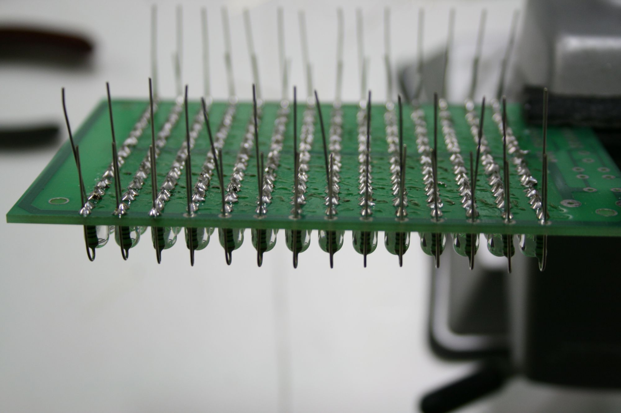 The resisters were long and didn’t fit when they were lying flat against the board, so I installed them vertically on mine. They seemed to do well like this.
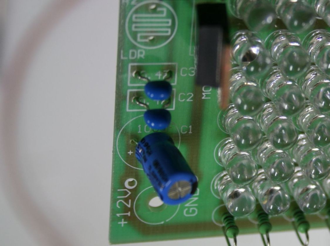
 These are the other items in place except for the photo cell in their correct position. The circuit for this kit was designed to turn ON when it got dark. So in other words the LEDs will not turn on so long as there is light falling on the photo cell. If you measure the resistance of the photo cell, it is low (i.e. it conducts electricity) when there is light and high (doesn’t conduct electricity) when it is dark. Since we want the IR light to come on when we turn the switch on, not necessarily when it is dark, I took this component out. This means that there is a very high resistance across the two points for this component on the board. Since the circuit is designed to allow electricity through to the LEDs when there is high resistance across these points (ie simulating when it is dark), you can leave the photo cell out, and the LED’s will simply come on when you provide them with power rather than when it is light and dark.NB: The integrated circuit is quite delicate and can be damaged by excessive heat so solder the socket of the integrated circuit to the board before plugging in the chip. Similarly try not to overheat the leads of the MOSFET so as not to damage the component.
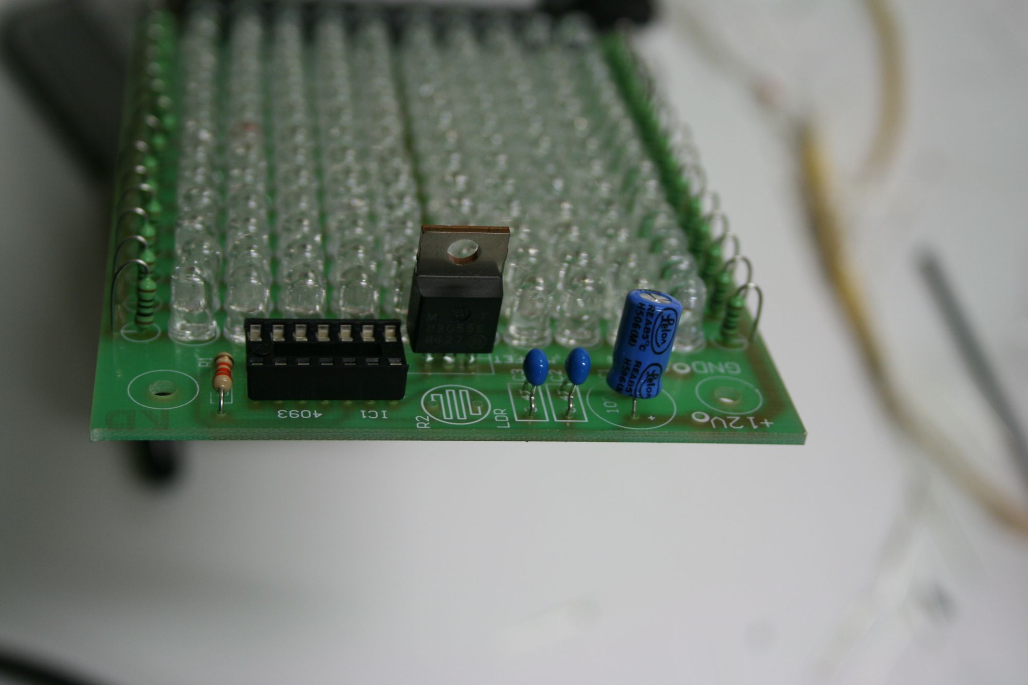
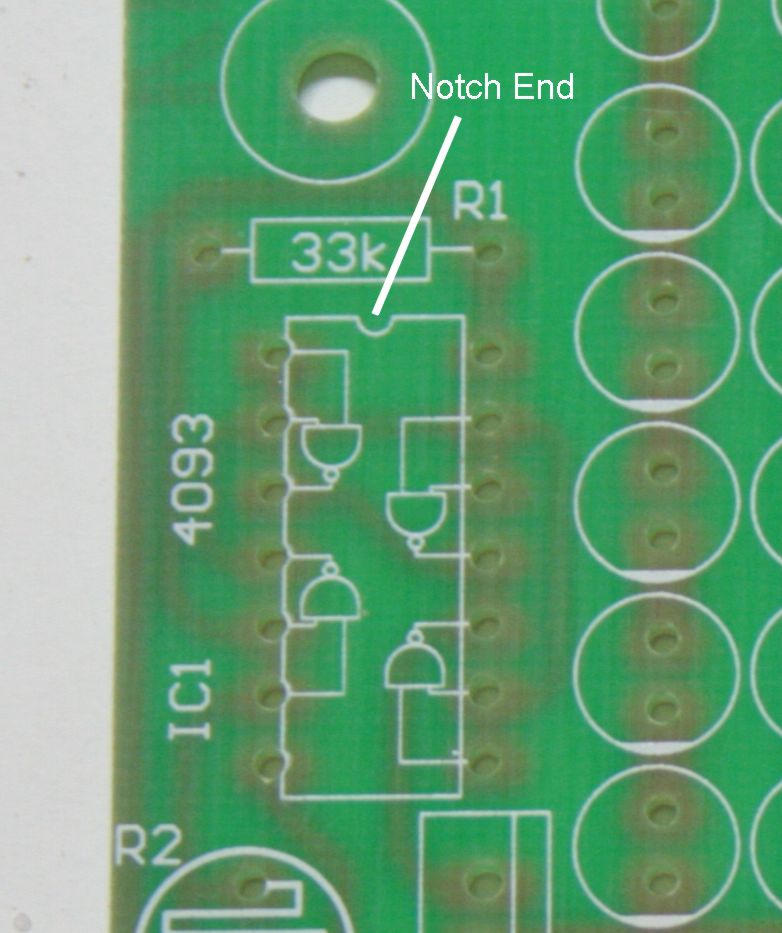
NB: There is a notch down one end of the integrated circuit socket showing which way around they go. Line these up with the notch shown on the circuit board
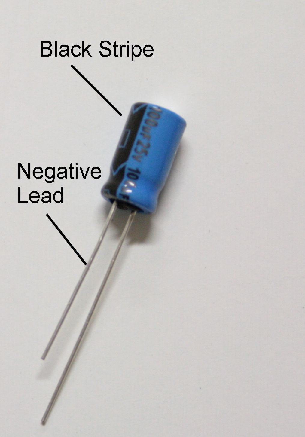
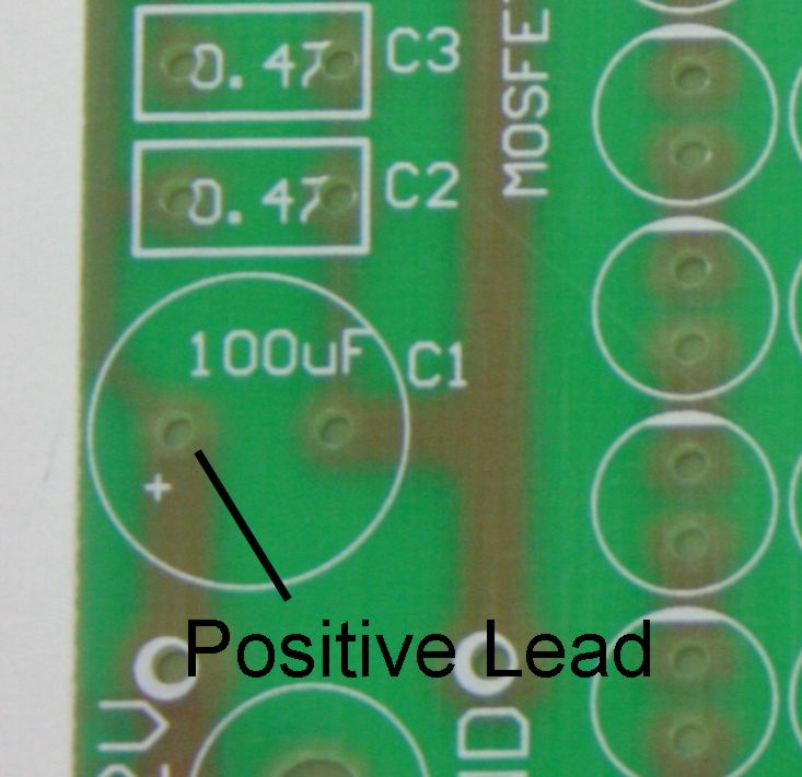
NB: The electrolyte capacitor has a polarity. The lead on the side with the black stripe and the shorter lead is the negative (ground) side. The other side is the positive side. These components can, and do explode if put the wrong way around.
These should then be installed in the appropriate slots in the circuit board.
There is no particular polarity for the ceramic capacitors.
Now that all the components are installed on the board we need to prepare the case that we will attach it to make our finished light source.
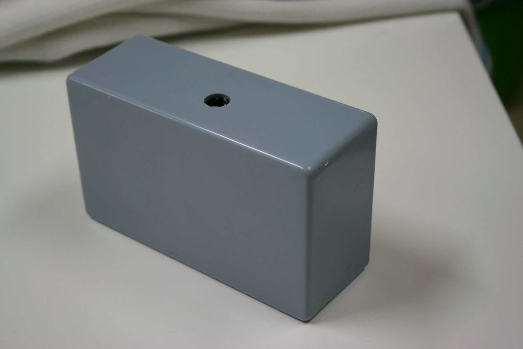
Below is the grey case that I got from Dick Smiths here in Australia but any electronics hobby store will have something similar. I have started by putting a hole in the top which is where the power supply socket will go. Make the hole whatever diameter your socket fits through.
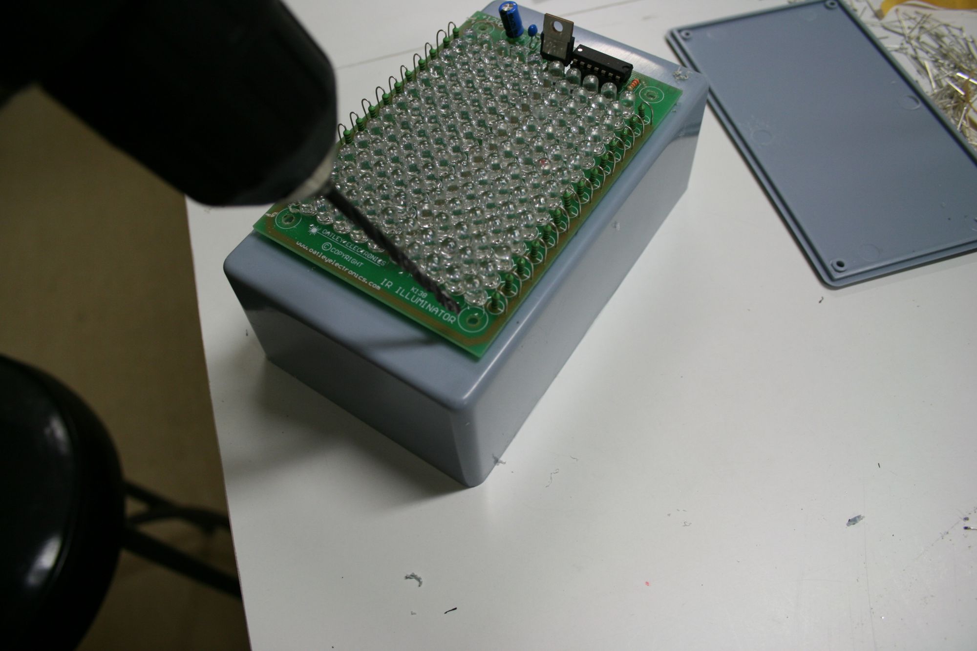
This is the case with the back opened up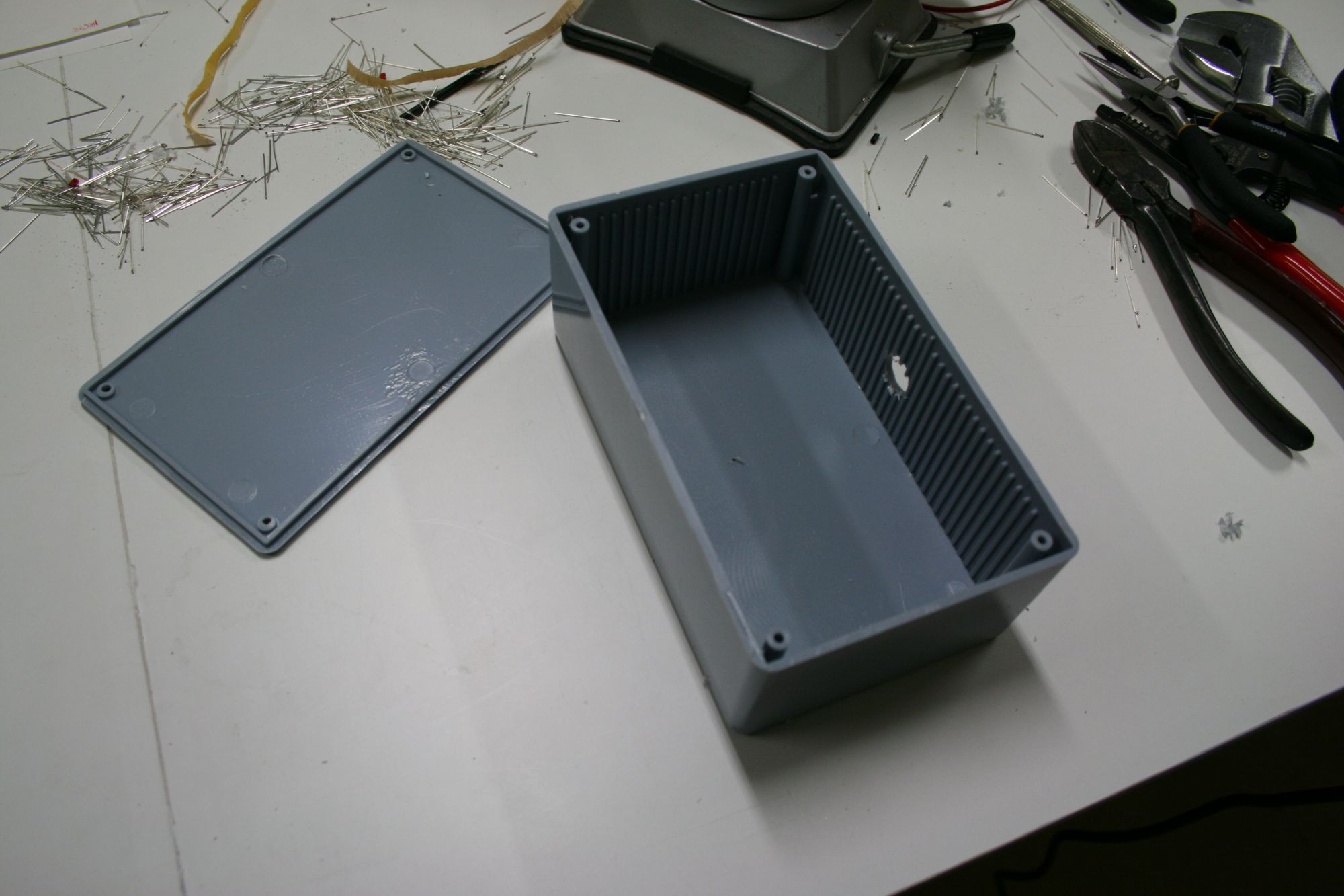 We will attach our circuit board with small bolts so we need to drill some holes in the front of the case through which these will go. I did that by using a drill bit the same size as the pre drilled holes already in the board and just holding the board in place as I drilled the four holes.
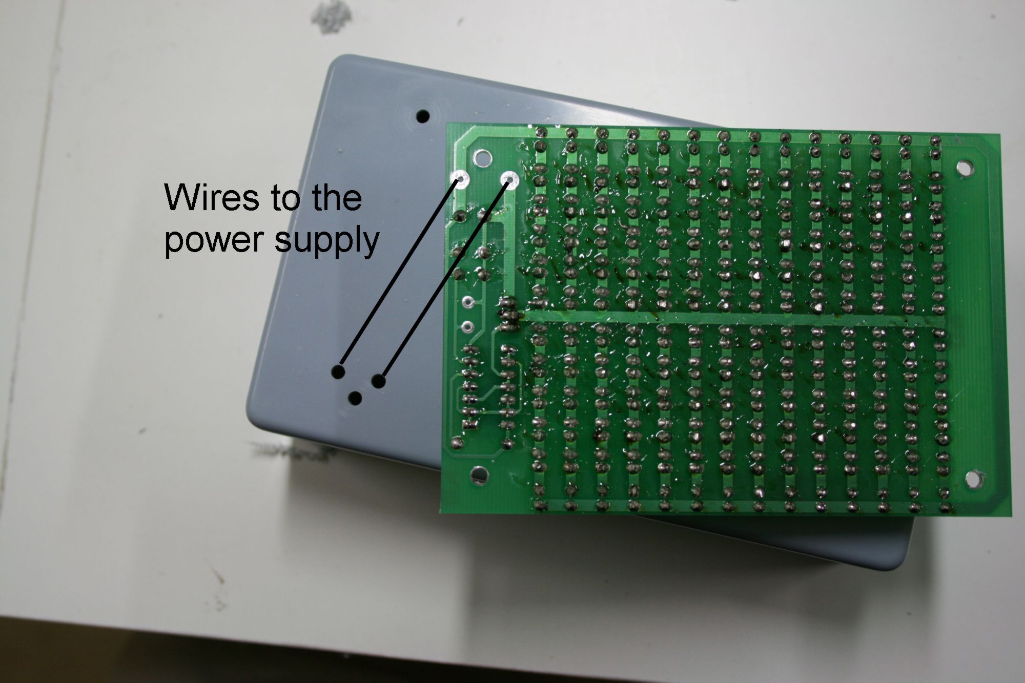
 I also drilled an extra couple of holes through which the power wires will go to get to the board. Note that the underside of the board is shown in the picture below so the location of the holes are flipped vertically.
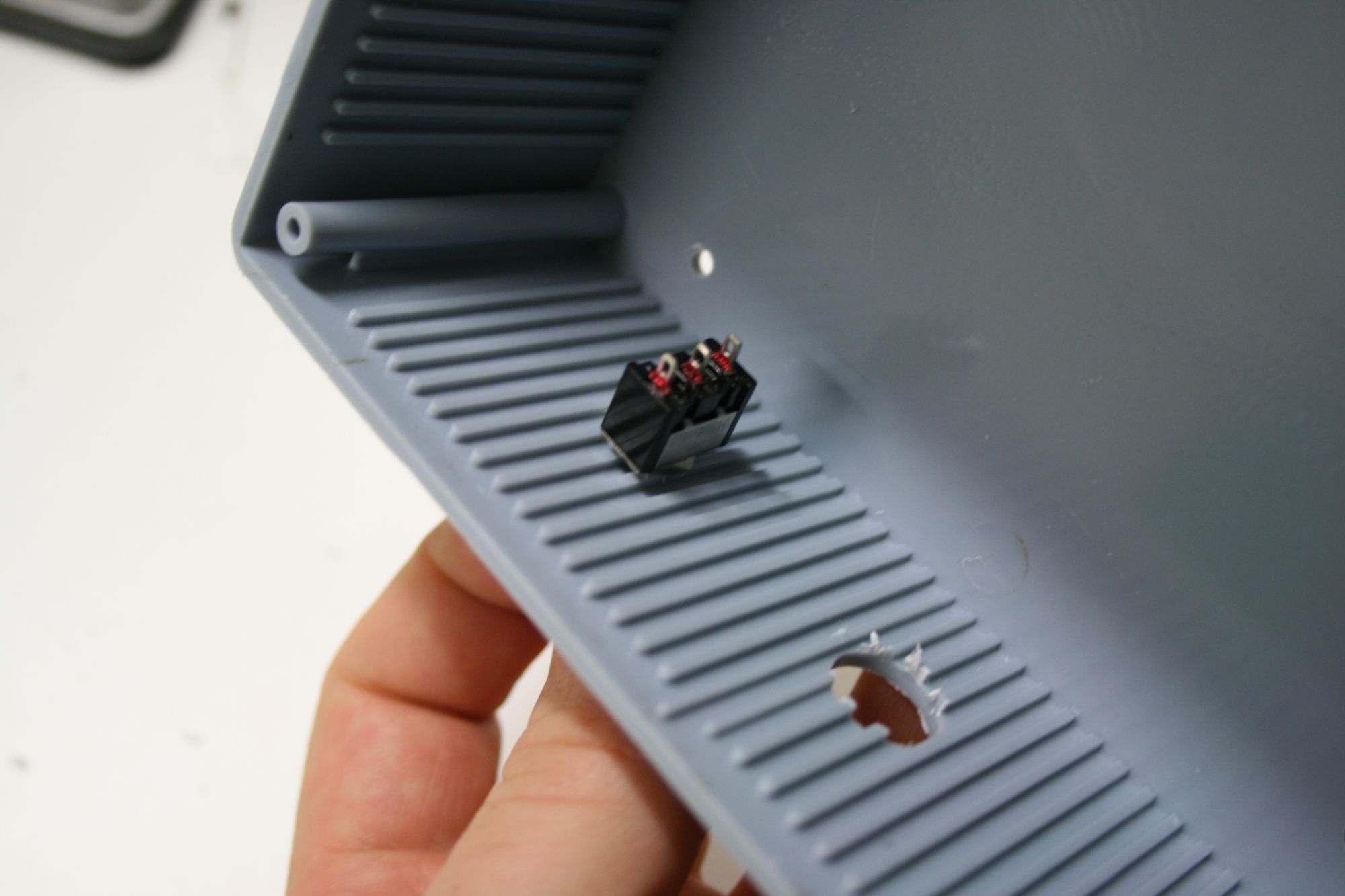
 Below is the inside of the case. I have made a second hole the right diameter for the switch to go through. The hole for the power socket can be seen beside it.
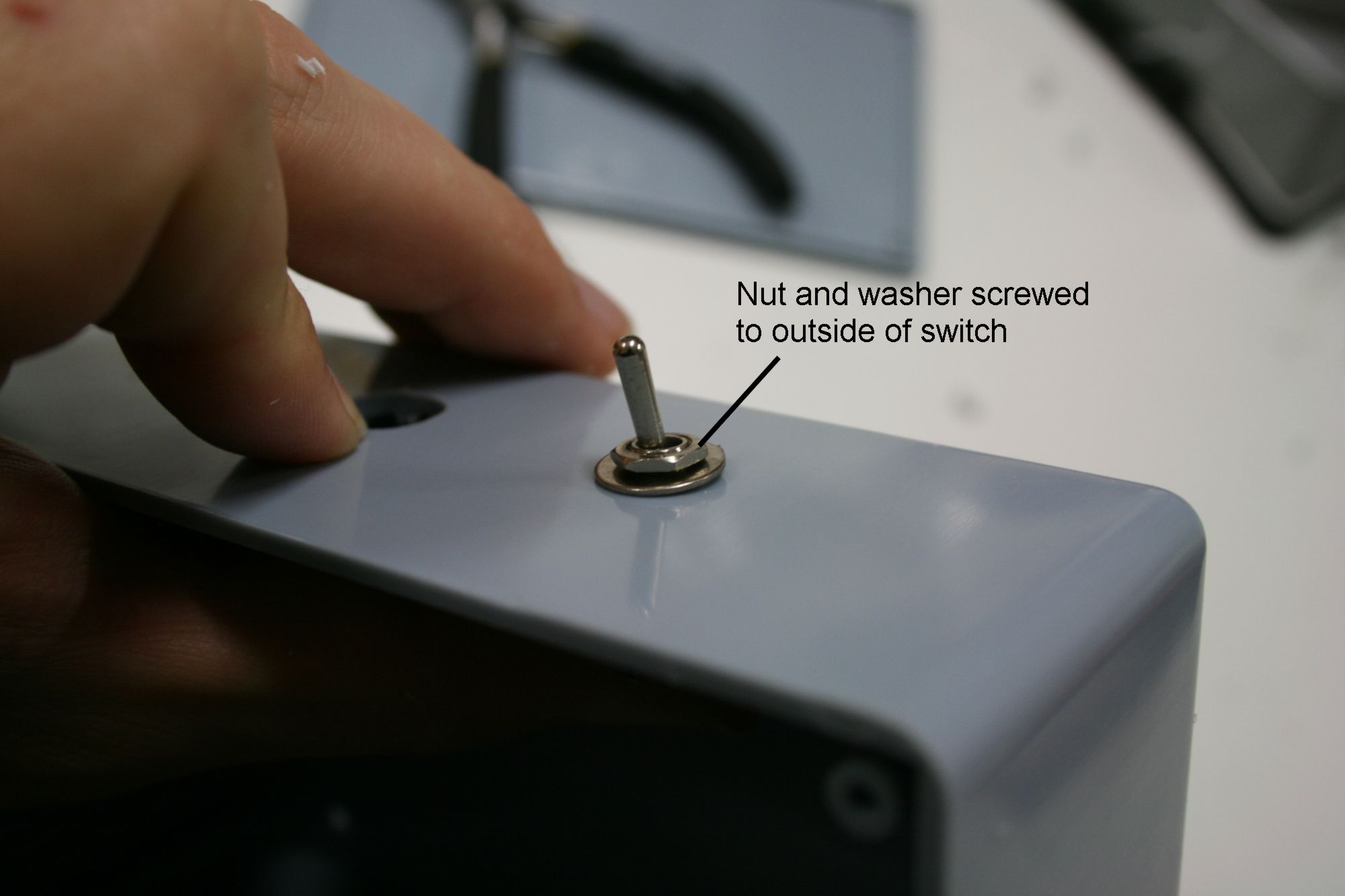
 When the body of the switch is in position the nuts can be fastened on the outside to hold it tight to the case, as shown below.
 Below I am putting the power supply socket into the hole I had made in the case.
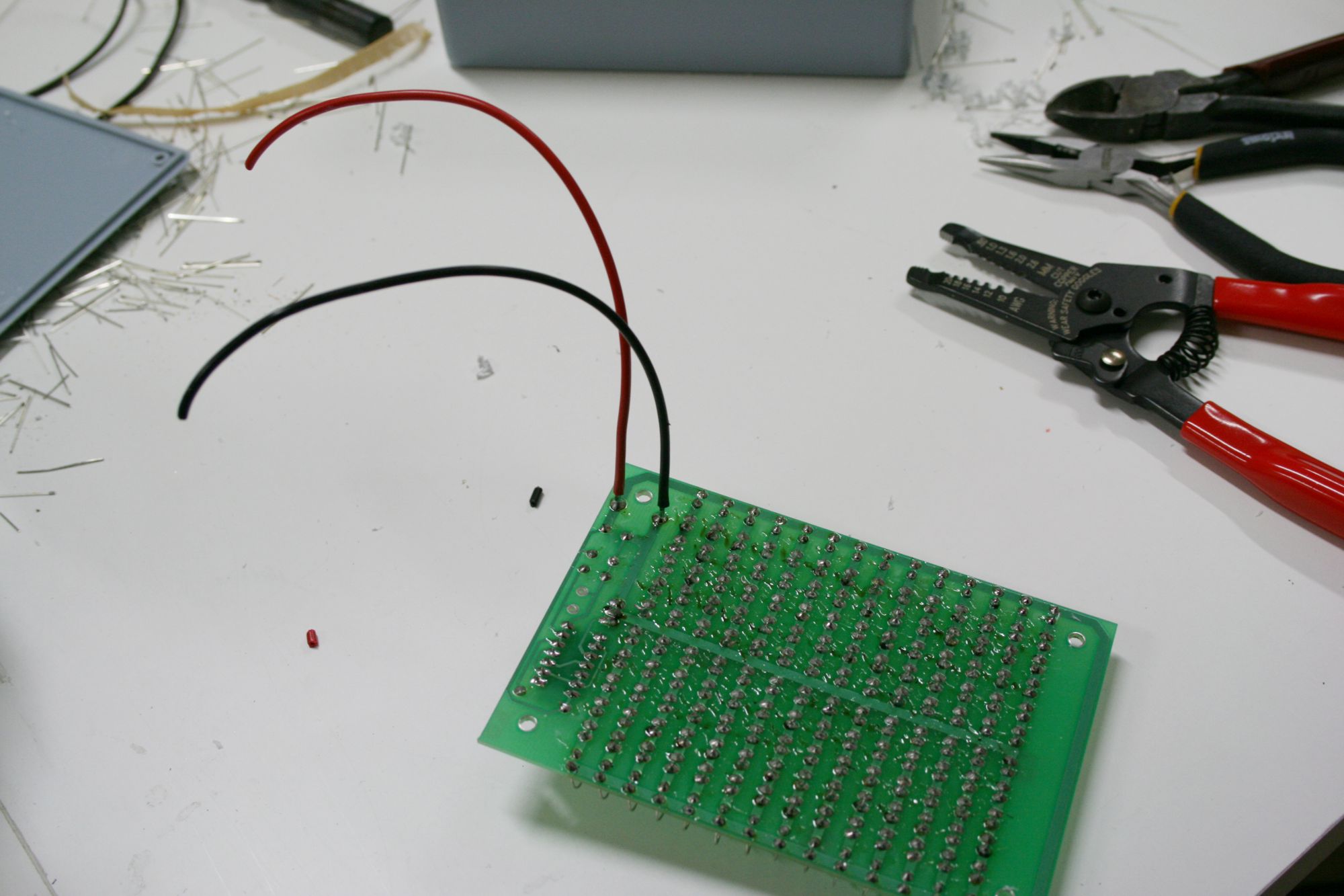
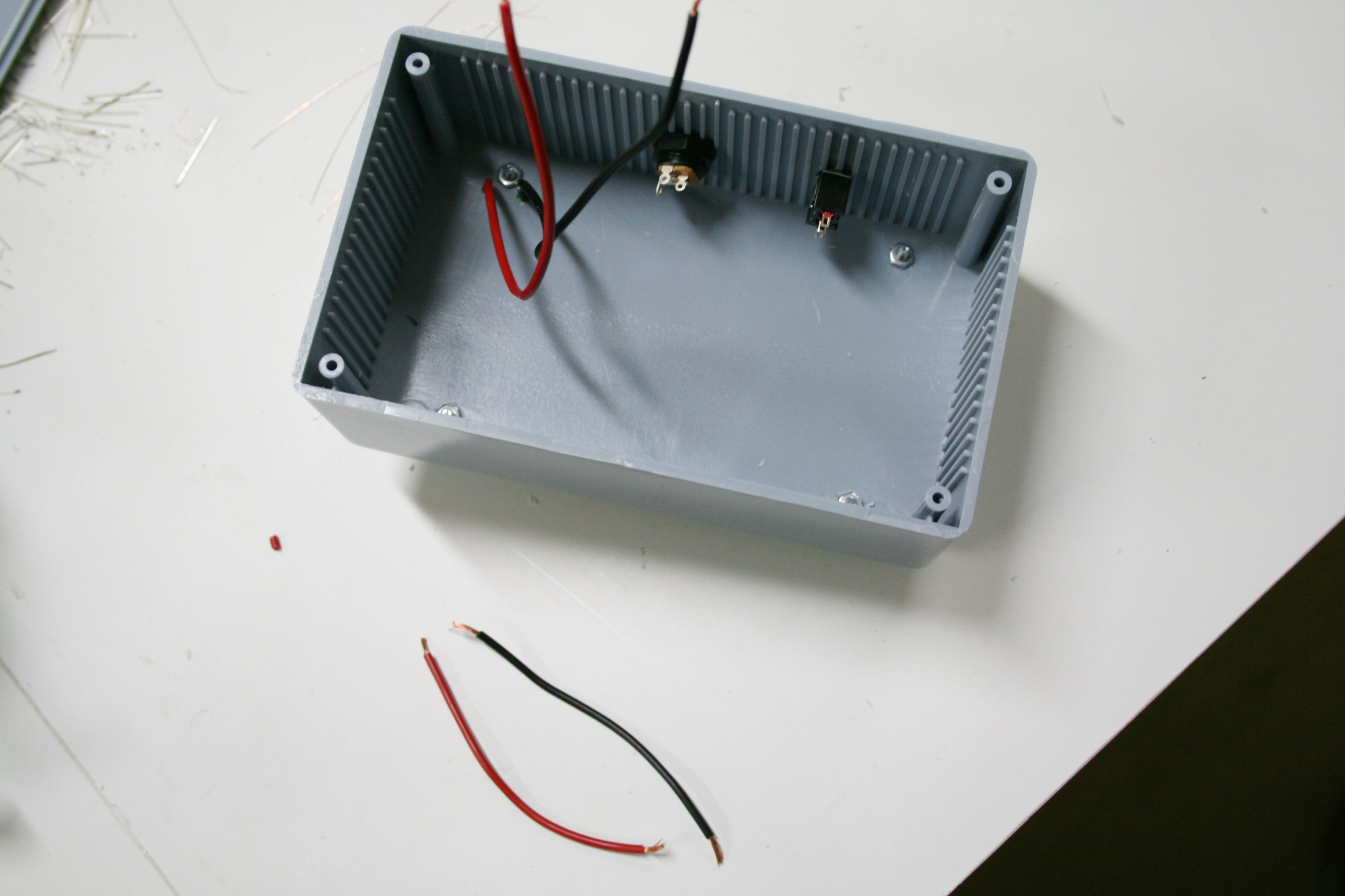
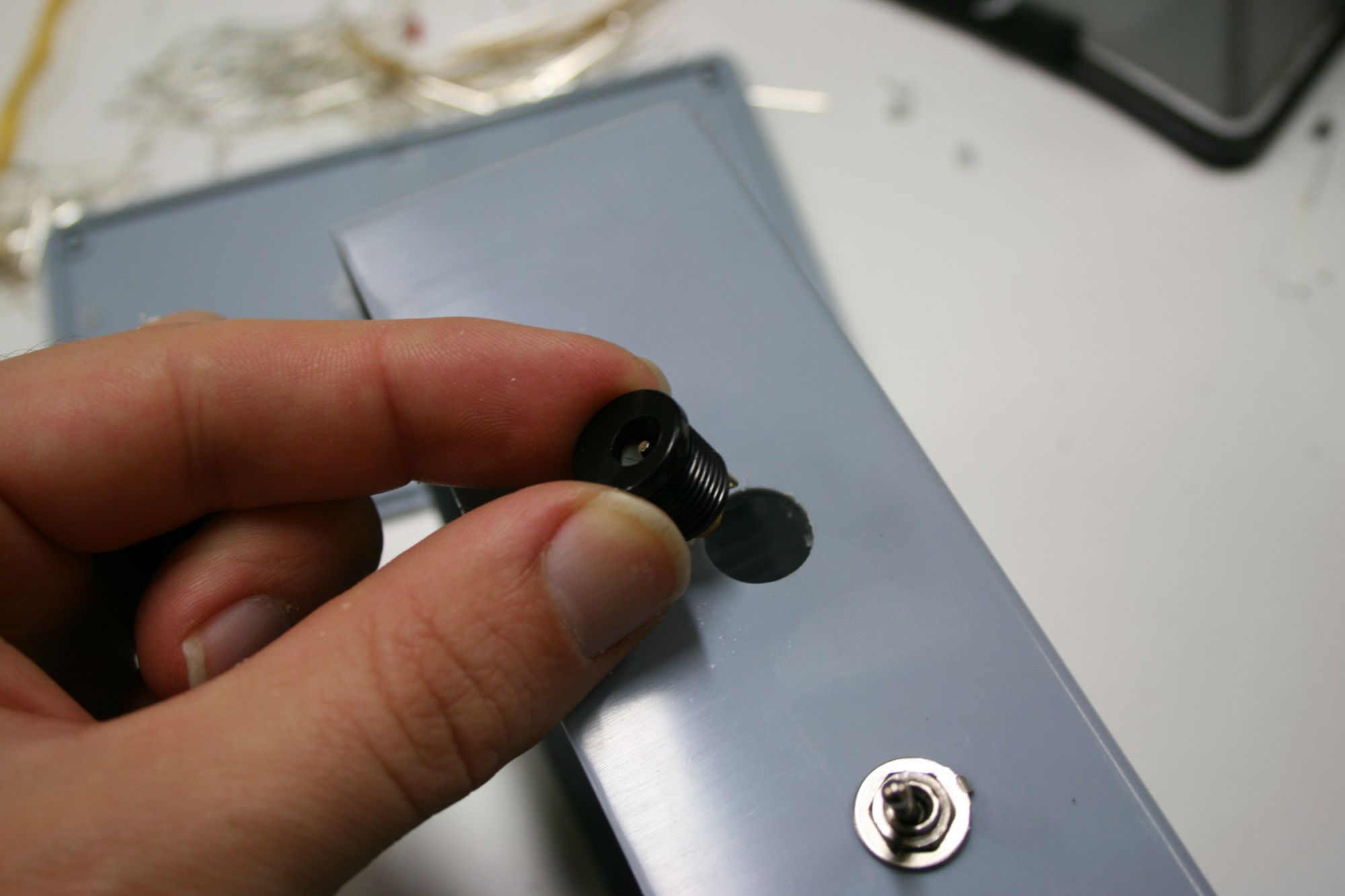 Next I solder two wires which will bring power to the circuit board. Note that these are soldered to the underside of the board, not to the top side like all the other components were.
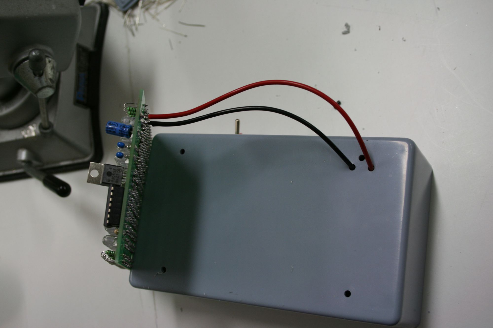
I then thread these wires through the holes I made earlier in the case.
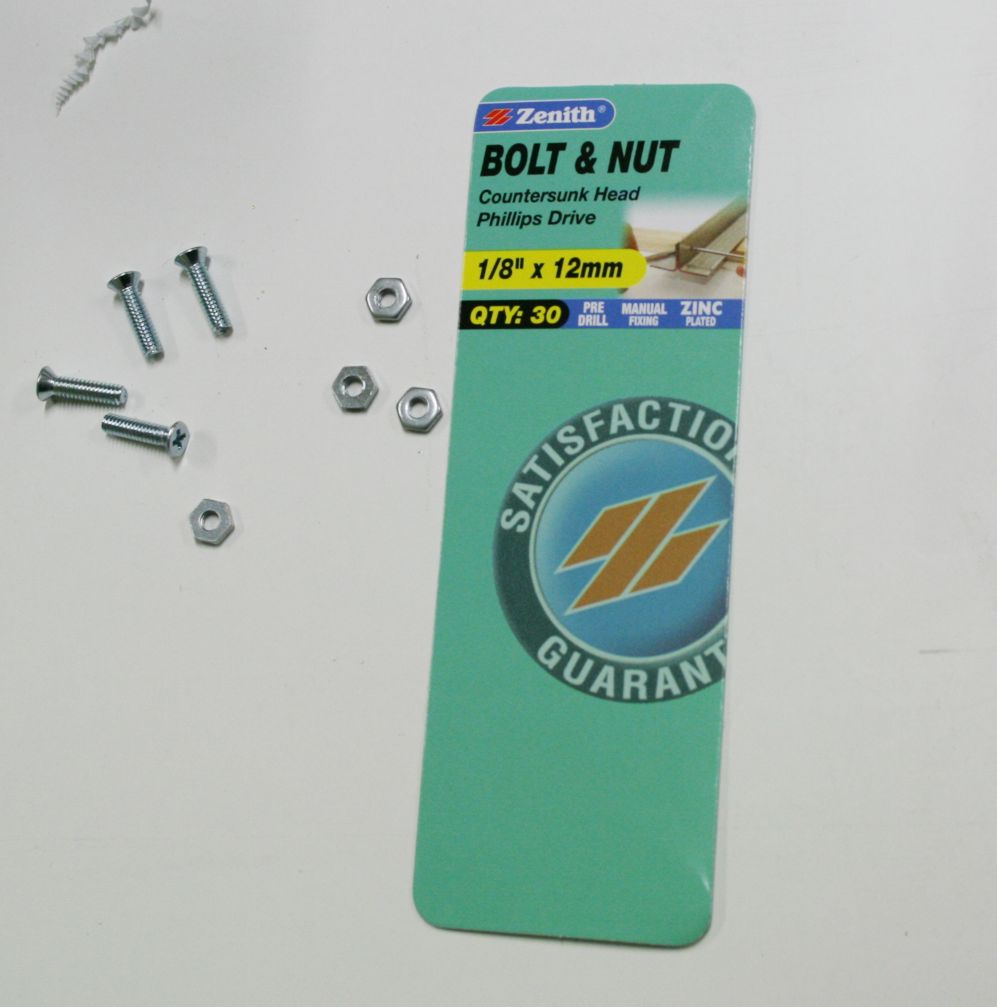
These are the bolts that I used to fasten the circuit board to the front of the case.
The circuit board bolted into place is shown below.
Note on Power Supplies
It is very important that the positive and negative terminals are connected up correctly. You will damage your components if they are not.
This means that the +ve terminal of your power supply has to be wired to the +ve terminal of your circuit board. To see which terminal is +ve have a look on your power supply. Most will tell you which terminal is +ve and which is -ve.
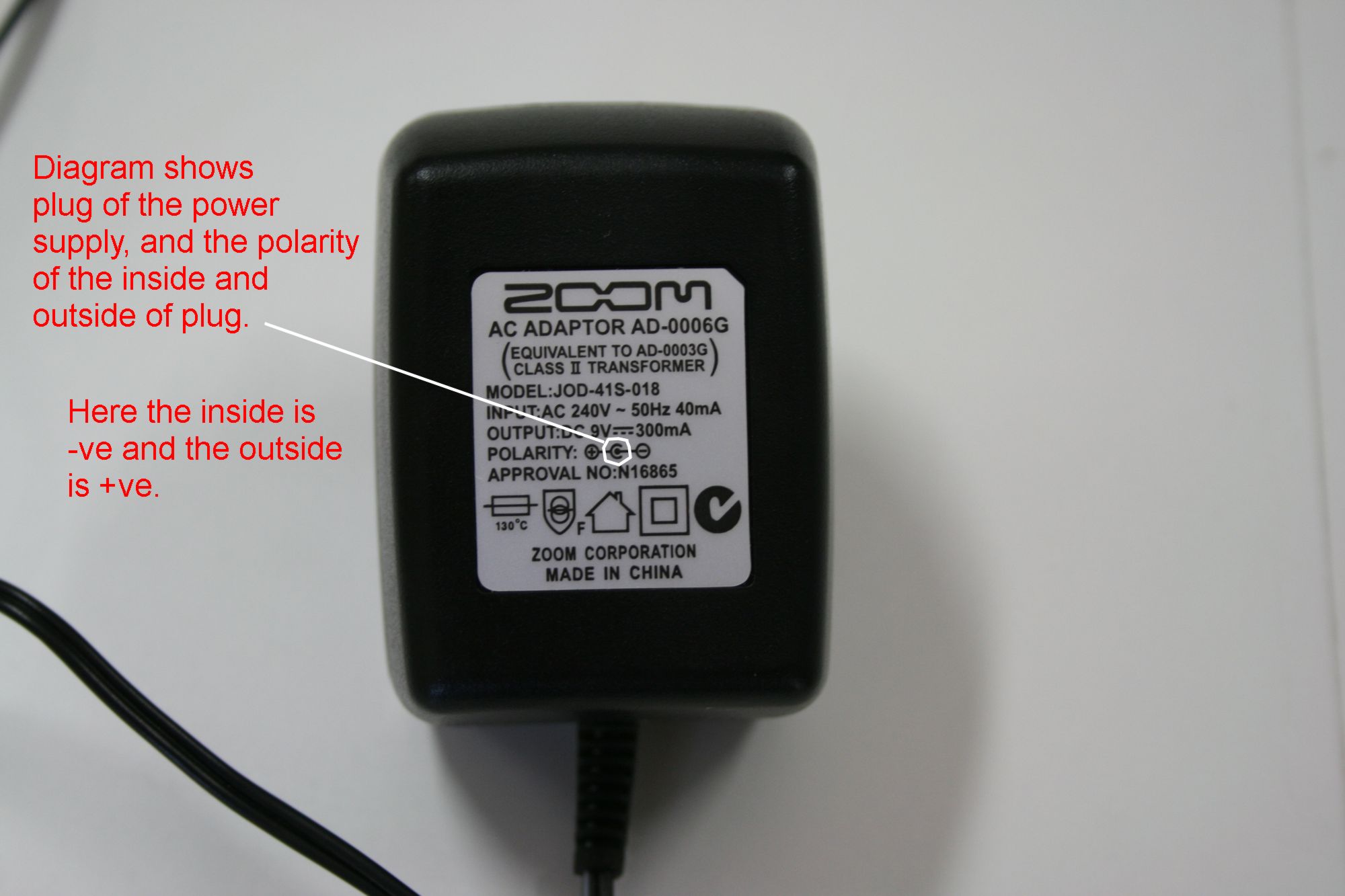
For example in the picture below, this power supply is for my 4 track field recorder. Note how the centre of the plug is –ve while the outside is +ve.
When I had a look at the power supply I bought through the electronics guy at work for these IR lights there was no diagram to show the polarity of the plug terminals.
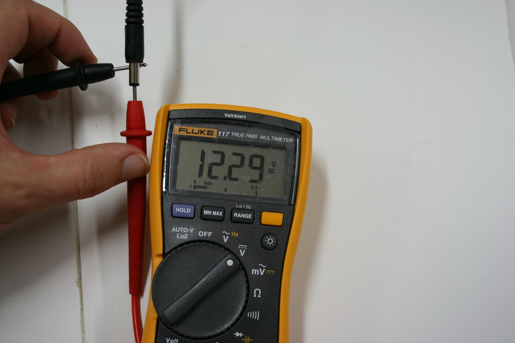
So I had to test it with my voltmeter. Placing the reference electrode (black) on the outside and the test electrode (red) in the middle I found that the output was +12.29V, showing that the middle of the plug was +ve compared to the outside of the plug.
These instructions for the assembly of an IR light source, therefore are for a power supply which is centre positive.
Wiring of the Sockets
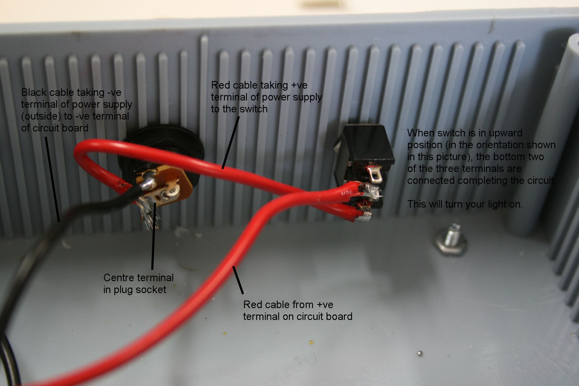
The wiring of the socket and the switch is relatively easy as all we are doing is running the circuit through the switch such that it is capable of breaking and completing the circuit.
NOTE: The power supply we will be using to provide the power for this light source has its positive terminal at the centre of its plug, while the outside of the plug is the negative terminal. When you are wiring your light it is vitally important that you check it is the same for your power supply. If the terminals are the other way around, then you will need to ensure that your switch the wiring around. Just ensure that the positive terminal of the power supply (which ever side of the plug that is in your case) is connected to the positive terminal of your circuit board. I will explain more about that below, but am just pointing out here that the these instructions are for a power supply which provides power from a centre positive plug.
The picture below shows how the power socket should be wired to the switch. Note the centre of the power supply (positive terminal) is going to the positive terminal of the circuit board.
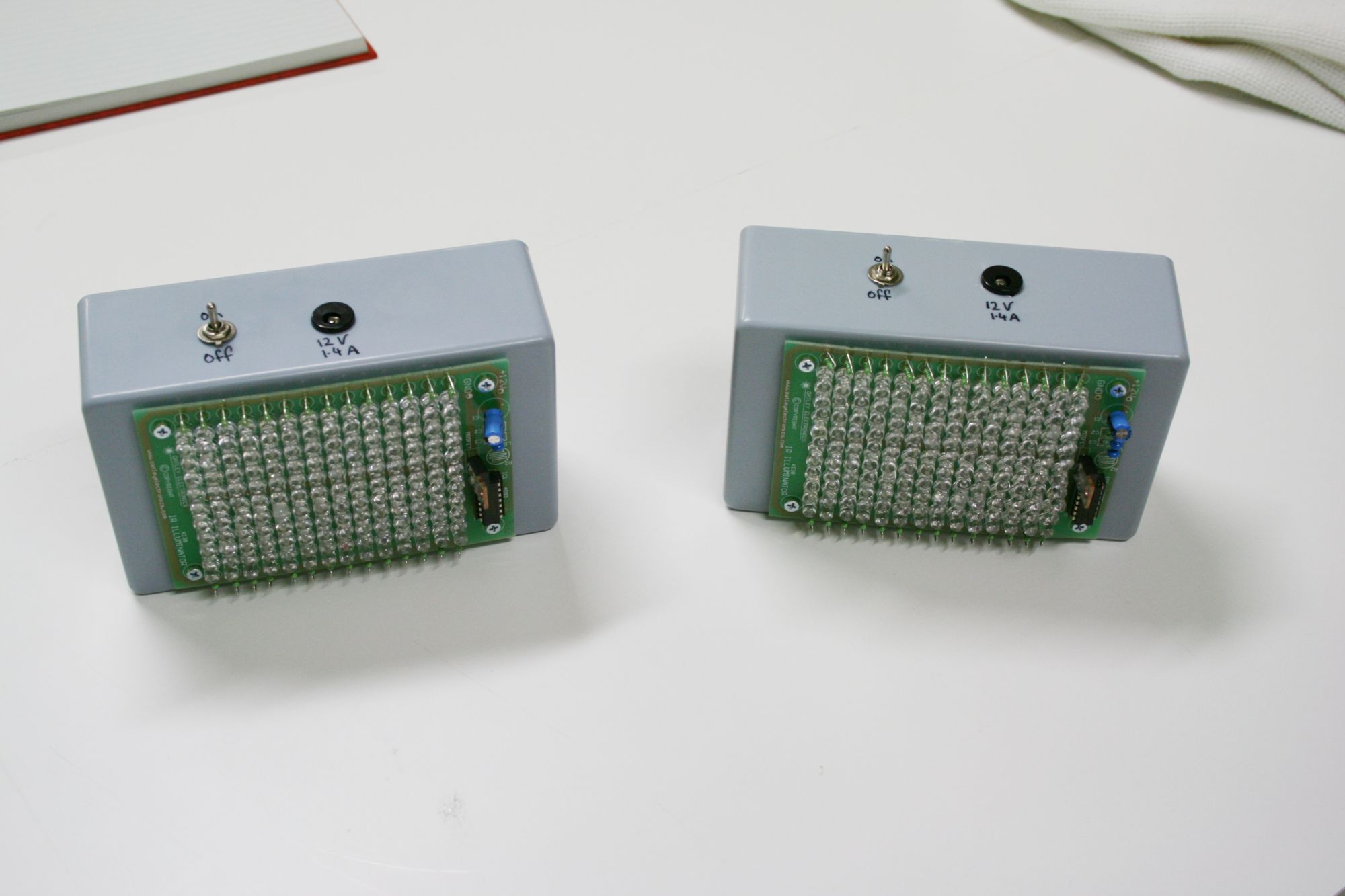
Lastly all there is to do is to screw on the back cover of the case. After doing all that twice I then ended up with two light sources shown below.
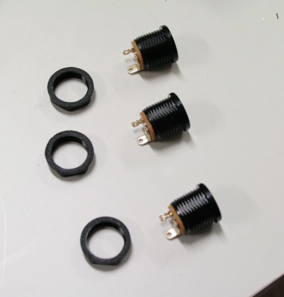
In order to minimize clutter I wanted to run both lights off a single power supply. As the describtion of the kit on the Oatley Electronics web site (http://secure.oatleyelectronics.com//product_info.php?products_id=671&osCsid=8d92ad64d22e7394c31ae68f9a75384b) says, each 140 LED light source will draw 1.4A of current. That meant I had to get a power supply that provided 12V of DC power at at least 2.8A of current. I got the power supply from the electronics guy at work, but again any specialist electronics hobby store will be able to hook you up with a power supply to meet your needs. In order to use a single power supply I also needed to make a double adapter to split the power supply between the two lights. To do this I bought four power plugs, 3 power sockets, a small case (as shown below) and 3m of electrical cable (not shown; any two-wire cable capable of carrying the current we are using will do)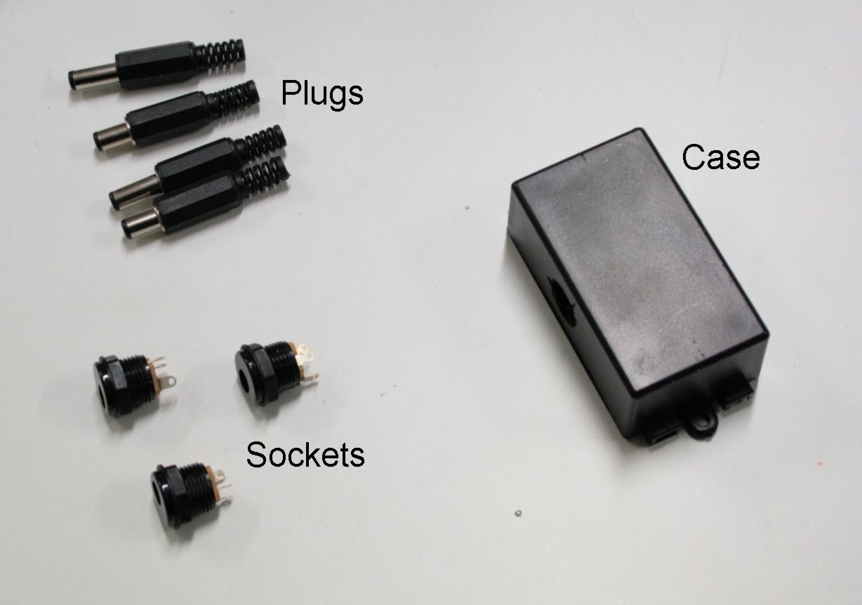 After drilling the same size holes that fit the diameter of the power sockets I removed the nuts from the sockets (as shown below)
 Then inserted them into the holes in the double adapter case.
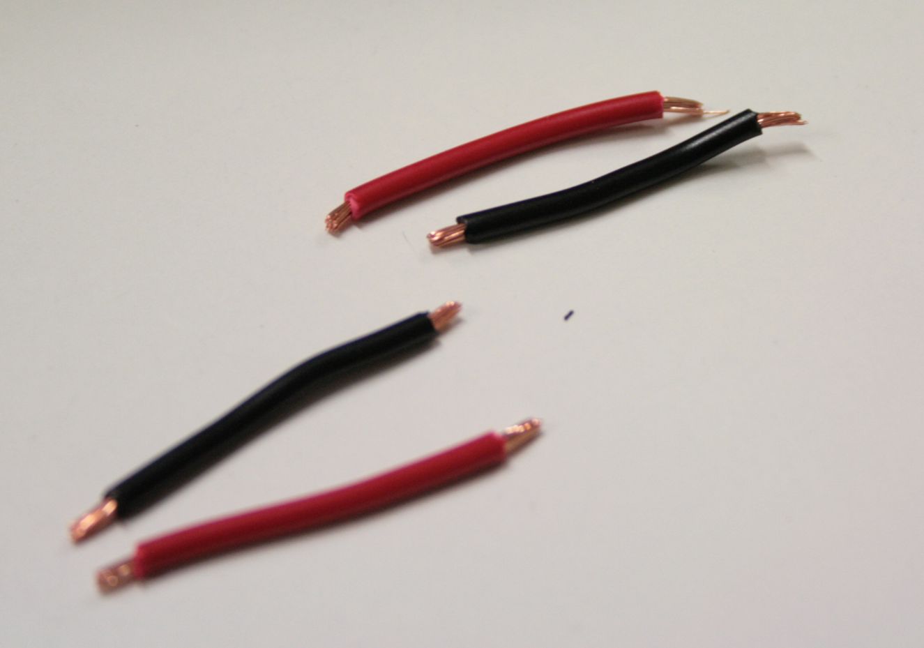
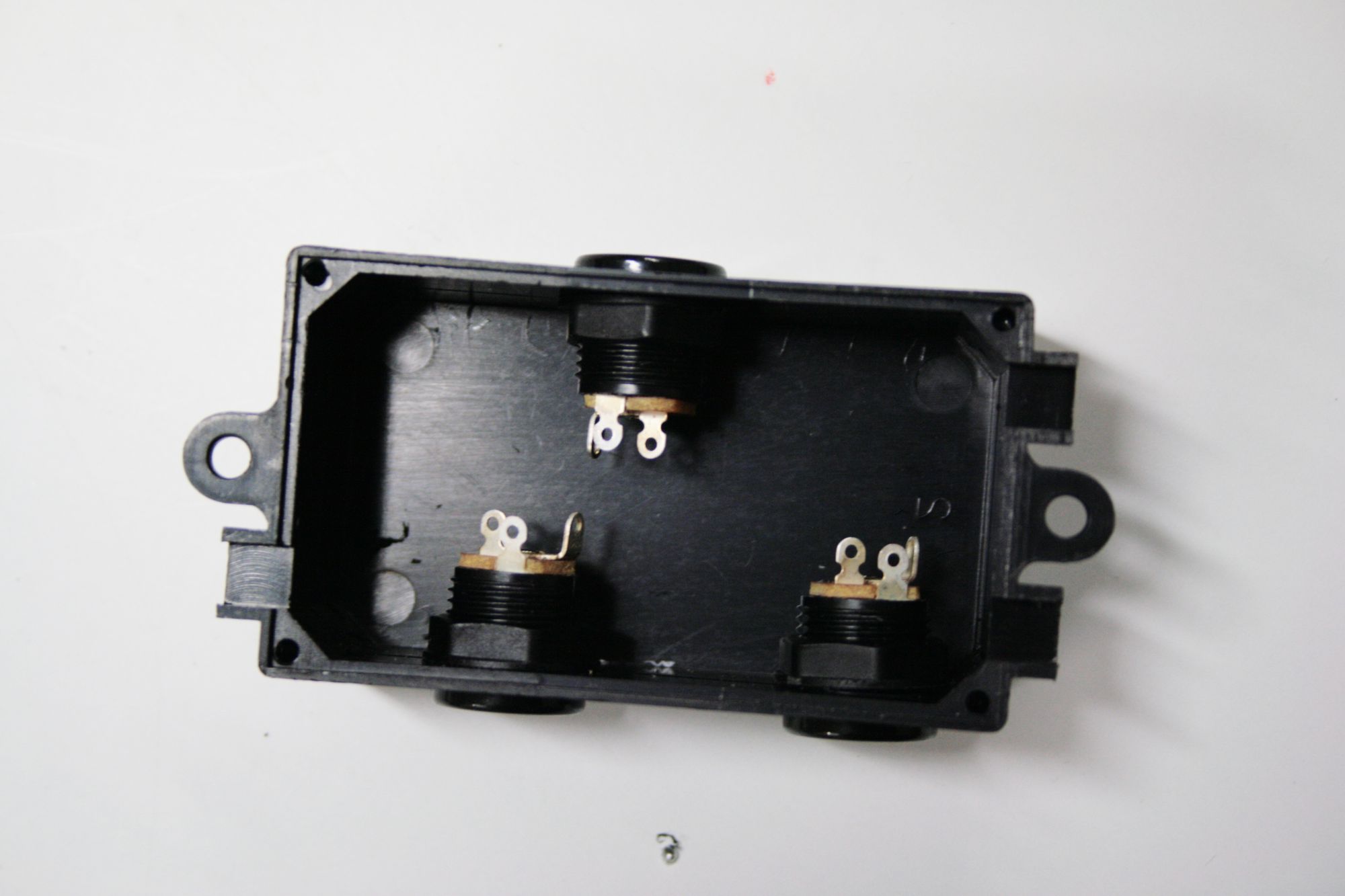 Then using short bits of wire as shown in this photo;
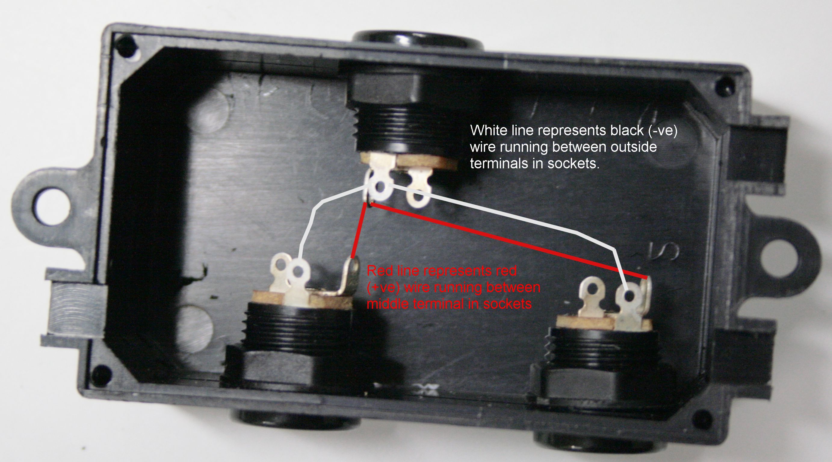
 I then wired the double adapter as indicated in this picture below
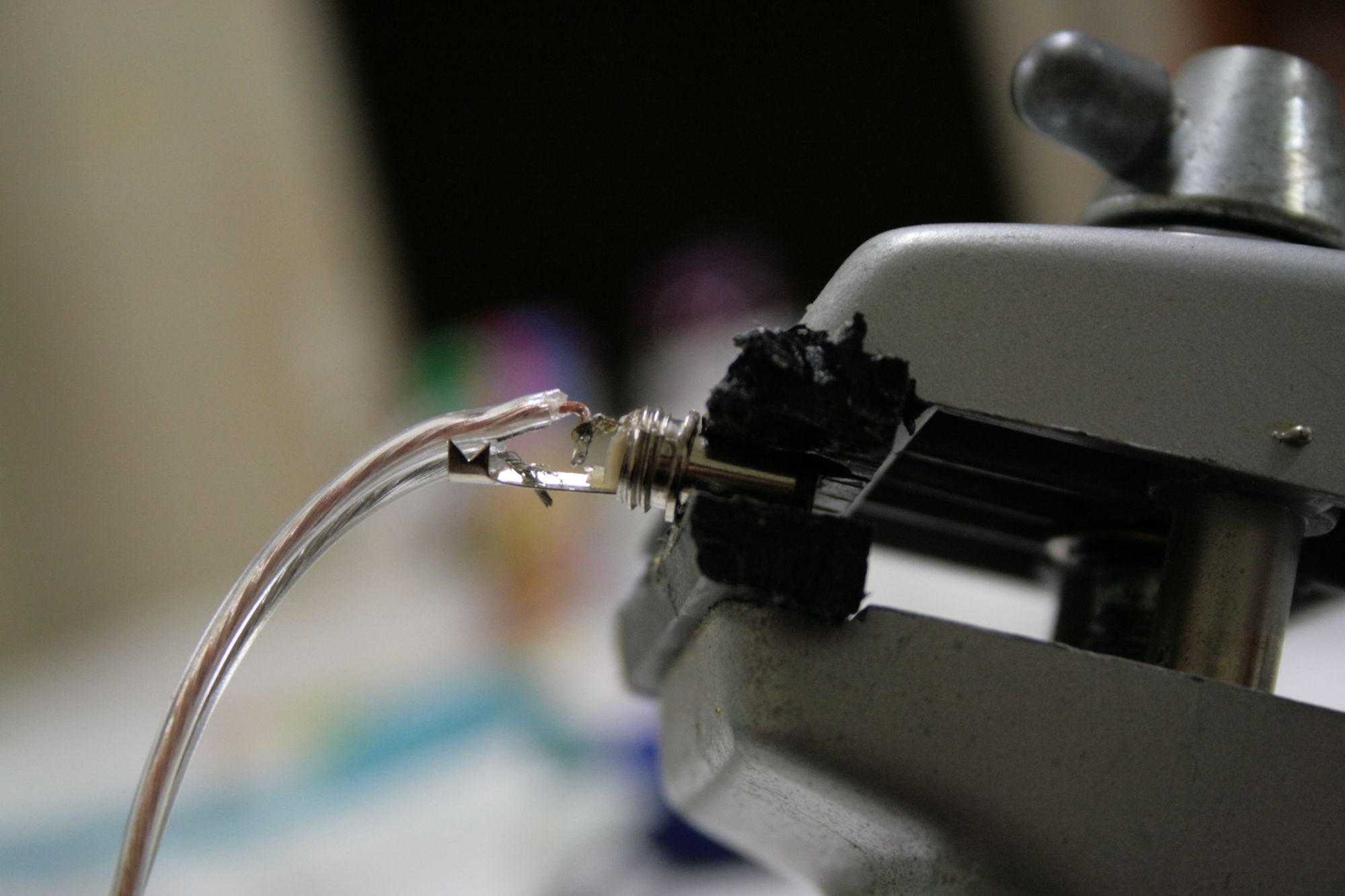
 Lastly I then took the black cover off the plugs and soldered the wire to the appropriate leads.
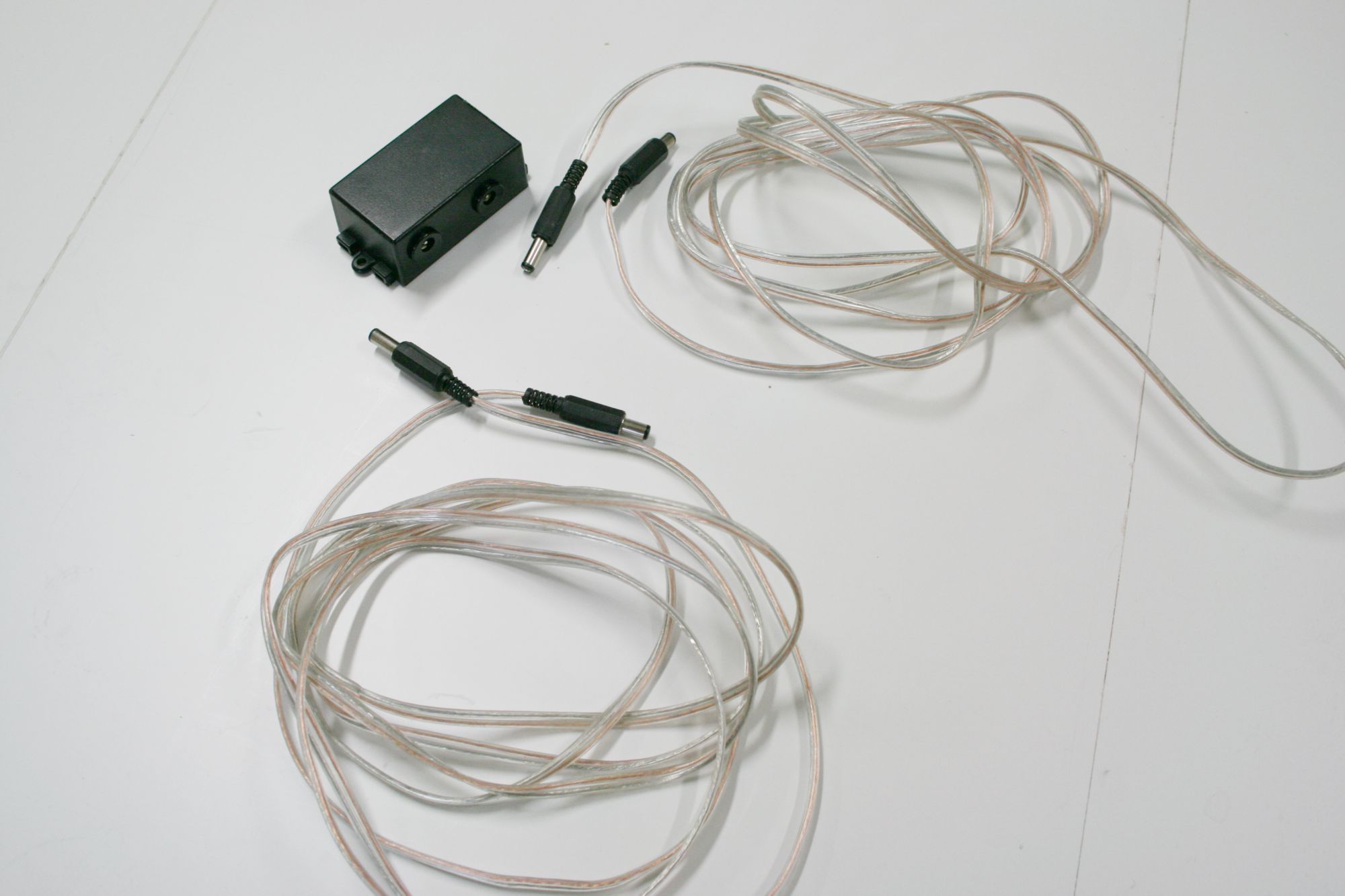
 Finished double adapter and wires are shown below:


4 responses so far ↓
1 Max // Aug 26, 2009 at 1:04 pm
Great tutorial, very detailed.
Just one question – why did you use the 850nm LED’s instead of the 880’s – “880nm IR LEDs (these are the LEDs that came with the kit which I replaced with 850nm LEDs since I wanted 140 of them and the kit only came with 35 LEDs).” Why not buy 105 @ 880nm?
2 FastLife // Sep 23, 2009 at 11:44 am
Hmm…I am not sure to be honest. Futurelec certainly have the 880nm IR LEDs. I had done a test previously using the completely invisible 920nm and 850nm and found the 850nm to be much brighter to the ccd chip of the camera. I suspect I simply stuck with the 850nm LEDs since I had tested this wavelength and found it to be the brightest of the two on the ccd chip. Without the technical specifications or having tried it I don’t know whether the 880nm would have been just as good. It could well have been.
3 Andrew // Mar 17, 2013 at 3:53 pm
What was the end result from this? Did it illuminate the area very well? (I can’t imagine LEDs being that bright, although I have been proved wrong before)
4 FastLife // Mar 17, 2013 at 4:23 pm
Hi Andrew. The end results was that these lamps lit up the room like a beacon, albeit in infrared so it was invisible to the human eye, but the camera could certainly see the result! One LED isn’t that bright, but 140LEDs are very bright. Bare in mind I had two of these so I actually had 280 LEDs. I will have to post some images of the result, and also some distance tests to see how far they can illuminate. The room I was trying to light was about 4m x 3m. Before these I was just using the single infra red light from my Sony night vision handycam, so there was this one central hotspot which was quite dim at 2m which is the distance I was using it but then the drop off around the hotspot was quite steep so all in all it was quite dim for the experiments I was trying to do. The LEDs worked brilliantly. Some other scientists at work borrowed them off me and used them for their dark experiments too. So they have put in quite a few hours now.